Stereoscopic display apparatus using LCD panel

a technology of lcd panel and stereoscopic display, applied in the field of electronic projection, can solve the problems of brightness and efficiency, added complexity and cost, and requirement for illumination, and achieve the effect of adding brightness

Inactive Publication Date: 2007-06-14
EASTMAN KODAK CO
View PDF26 Cites 125 Cited by
  • Summary
  • Abstract
  • Description
  • Claims
  • Application Information

AI Technical Summary

Benefits of technology

[0033] It is an advantage of the present invention that it allows added brightness for the projected stereoscopic image. Various types of light sources could be used.

Problems solved by technology

Yet another factor that tends to bias projector development efforts toward miniaturized devices relates to the dimensional characteristics of the film that is to be replaced.
However, this interest in LCOS LCD or DMD devices also results from an unquestioned assumption on the part of designers that image formation at smaller dimensions is most favorable.
One problem inherent with the use of miniaturized LCOS and DMD spatial light modulators relates to brightness and efficiency.
Added complexity and cost result from the requirement to handle illumination at larger angles.
A related consideration is that image-forming components also have limitations on energy density.
That is, a level of brightness beyond a certain threshold level can damage the device itself.
Heat build-up must also be prevented, since this would cause distortion of the image, color aberrations, and could shorten the lifespan of the light modulator and its support components.
In particular, the behavior of the absorptive polarization components used can be significantly compromised by heat build-up.
Again, this adds cost and complexity to optical system design.
Still other related problems with LCOS LCDs relate to the high angles of modulated light needed.
The mechanism for image formation in LCD devices and the inherent birefringence of the LCD itself limit the contrast and color quality available from these devices when incident illumination is highly angular.
This, however, further increases the complexity and cost of the projection system.
However, in a number of cases, these apparatus have been proposed for specialized applications, and are not intended for use in high-end digital cinema applications.
While each of these examples employs a larger LC panel for image modulation, none of these designs is intended for motion picture projection at high resolution, having good brightness levels, color comparable to that of conventional motion picture film, acceptable contrast, and a high level of overall image quality.
Thus, it can be seen that, although digital cinema projection apparatus solutions have focused on the use of LCOS LCDs for image forming, there are inherent limitations in brightness and efficiency when using LCOS LCD components for this purpose.
While projection apparatus using TFT LC panels have been disclosed, these have not been well suited to the demanding brightness requirements of high-performance digital cinema projection.
Other problems relate to the nature of light modulation by the TFT LC device and to the support components necessary for high brightness applications requiring high levels of image quality.
For example, the use of absorptive polarizers directly attached to the TFT panels, as these devices are commonly provided, is disadvantageous for image quality.
Heat absorption from these films, typically exceeding 20% of the light energy, causes consequent heating of the LCD materials, resulting in a loss of contrast and contrast uniformity.
Conventional stereoscopic imaging systems using electronic display components are typically inefficient and provide low brightness levels.

Method used


Image

  • Stereoscopic display apparatus using LCD panel
  • Stereoscopic display apparatus using LCD panel
  • Stereoscopic display apparatus using LCD panel

Examples


Embodiment Construction

[0053] The present description is directed in particular to elements forming part of, or cooperating more directly with, apparatus in accordance with the invention. It is to be understood that elements not specifically shown or described may take various forms well known to those skilled in the art.

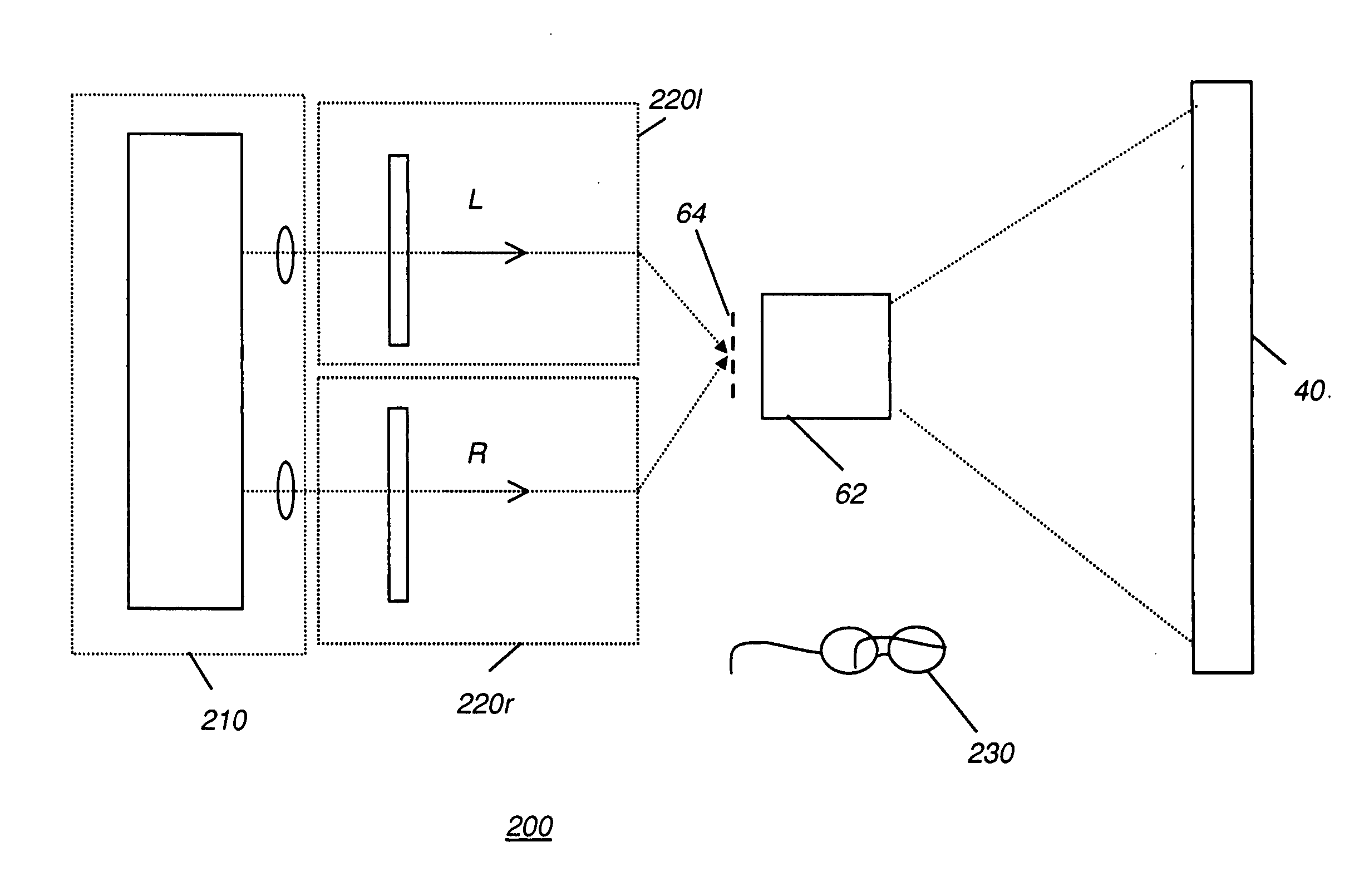
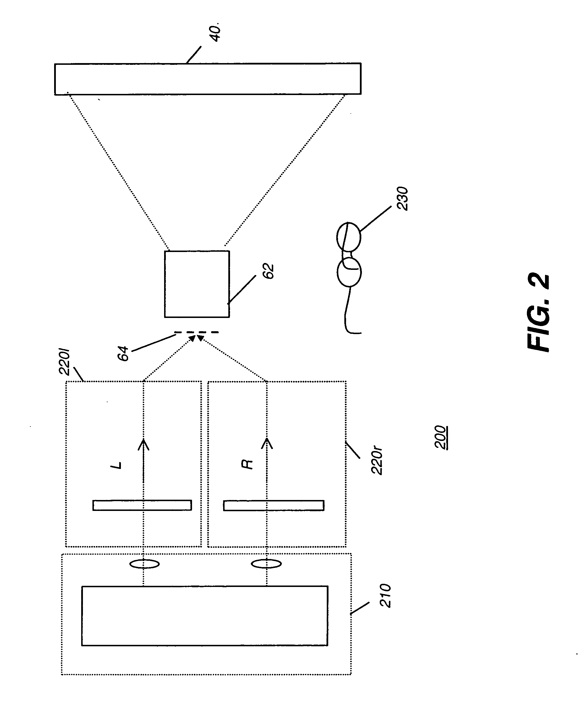
[0054] The present invention adapts one or more TFT LC devices for use in stereoscopic projection. The major components of a stereoscopic imaging apparatus 200 are shown in the block diagram of FIG. 2. An illumination source 210 splits light, according to a characteristic property such as polarization or spectral content, into two channels, a left channel and a right channel. Each channel is provided for modulation: the left channel to a modulation apparatus 220l and the right channel to a modulation apparatus 220r. Modulation apparatus 220l and 220r operate to form an image 64, such as an intermediate image as shown in FIG. 2, that is projected onto display surface 40 by a projection le...


PUM


Abstract

A stereoscopic imaging apparatus (200) has an illumination source (110) providing polarized illumination beams and at least one uniformizing element (22) for uniformizing first and second illumination beams. A left channel modulation apparatus (220l) modulates the first polarized illumination beam to provide the left eye portion of the stereoscopic image and a right channel modulation apparatus (220r) modulates the second polarized illumination beam to provide the right eye portion. Each channel modulation apparatus has a color separator (78) for separating the polarized illumination beam into at least a first component wavelength illumination and a second component wavelength illumination. Each channel modulation apparatus also has at least two component wavelength modulating sections, each component wavelength modulating section being a portion of a monochrome transmissive liquid crystal modulator panel (60) that accepts a corresponding component wavelength illumination and modulates the component wavelength illumination to provide a modulated component wavelength beam.

Description

CROSS REFERENCE TO RELATED APPLICATIONS [0001] The present application is related to pending U.S. patent application Ser. No. 11 / 120,331, filed May 3, 2005, entitled DISPLAY APPARATUS USING LCD PANEL, by Silverstein et al., the disclosure of which is incorporated herein.FIELD OF THE INVENTION [0002] This invention generally relates to electronic projection and more particularly relates to a stereoscopic electronic projection apparatus using an LC modulator panel or panels for forming a full color stereoscopic projection image. BACKGROUND OF THE INVENTION [0003] Liquid crystal (LC) technology has been successfully harnessed to serve numerous display applications, ranging from monochrome alphanumeric display panels, to laptop computers, and even to large-scale full color displays. As is well known, an LC device forms an image as an array of pixels by selectively modulating the polarization state of incident light for each corresponding pixel. Continuing improvements of LC technology h...

Claims


Application Information

Patent Timeline
Patent Type & Authority Applications(United States)
IPC IPC(8): G03B21/00G02B30/25H04N13/363
CPCH04N13/0431H04N13/0434H04N13/0459H04N13/337H04N13/334H04N13/363H04N13/00G03B21/00
Inventor SILVERSTEIN, BARRY D.
Owner EASTMAN KODAK CO
Why Eureka
Try Eureka