Image stabilizer, lens device and imager apparatus

a technology of image stabilization and lens device, which is applied in the field of image stabilization, lens device and image stabilization apparatus, can solve the problems of difficult to miniaturize the whole of the image stabilization apparatus, and achieve the effect of preventing the image stabilization devi

Inactive Publication Date: 2007-06-14
SONY CORP
View PDF9 Cites 50 Cited by
  • Summary
  • Abstract
  • Description
  • Claims
  • Application Information

AI Technical Summary

Benefits of technology

[0010] Japanese Patent Application Publication No. 2000-258813 discloses another example of an image stabilizer in related art, for example. In this Patent Reference, there is described one relating to an image stabilizer used for optical equipment and a lens barrel using the image stabilizer. The image stabilizer described in this Patent Reference (hereinafter referred to as “a second related-art example”) is an image stabilizer which stabilizes images by moving part of a imaging lens to the inside of a surface perpendicular to an optical axis, including: a lens holding frame, a first guide, a second guide, a first driver, a second driver, and a position detector. The lens holding frame holds a correcting lens. The first guide guides the lens holding frame to move in a first direction within a surface perpendicular to the optical axis. The second guide guides the lens holding frame to move in a second direction perpendicular to the first direction. The first driver and second driver drive the lens holding frame in the first and second directions, respectively. The position detector detects the position of the correcting lens. In this image stabilizer, the first guide and the second driver, or the second guide and the first driver are arranged to partially overlap, when seen from an optical axis direction.
[0012] However, regarding the aforementioned first and second related-art examples, a holding frame which has a correcting lens is guided and supported in a movable manner in a first direction and second direction perpendicular to each other, and the first and second directions are set to be the same as the directions in which the correcting lens is moved by first and second drivers. Hence, there has been a problem that the whole of an image stabilizer becomes large and it may be difficult to be small-sized.
[0013] Such problem will be explained in detail using FIGS. 19A and 19B. FIGS. 19A and 19B schematically show the moving range of a correcting lens CL in a first direction X and in a second direction Y perpendicular to each other. In FIG. 19A, regarding the two axes perpendicular to each other, the first direction X is plotted on the horizontal axis and the second direction Y is plotted on the vertical axis. With those X and Y axes being reference axes, moving range in the rightward and upward directions thereof is designated as the positive (+) and moving range in the leftward and downward directions thereof is designated as the negative (−). A quadrilateral CL shown with a broken line represents a correcting lens being in focus without an image blur. With the position of this correcting lens CL being a reference, a cor

Problems solved by technology

In related art, there is one-to-one relationship between moving range of a correcting lens CL and driving force required for the movement, and so the movement-

Method used


Image

  • Image stabilizer, lens device and imager apparatus
  • Image stabilizer, lens device and imager apparatus
  • Image stabilizer, lens device and imager apparatus

Examples


first embodiment

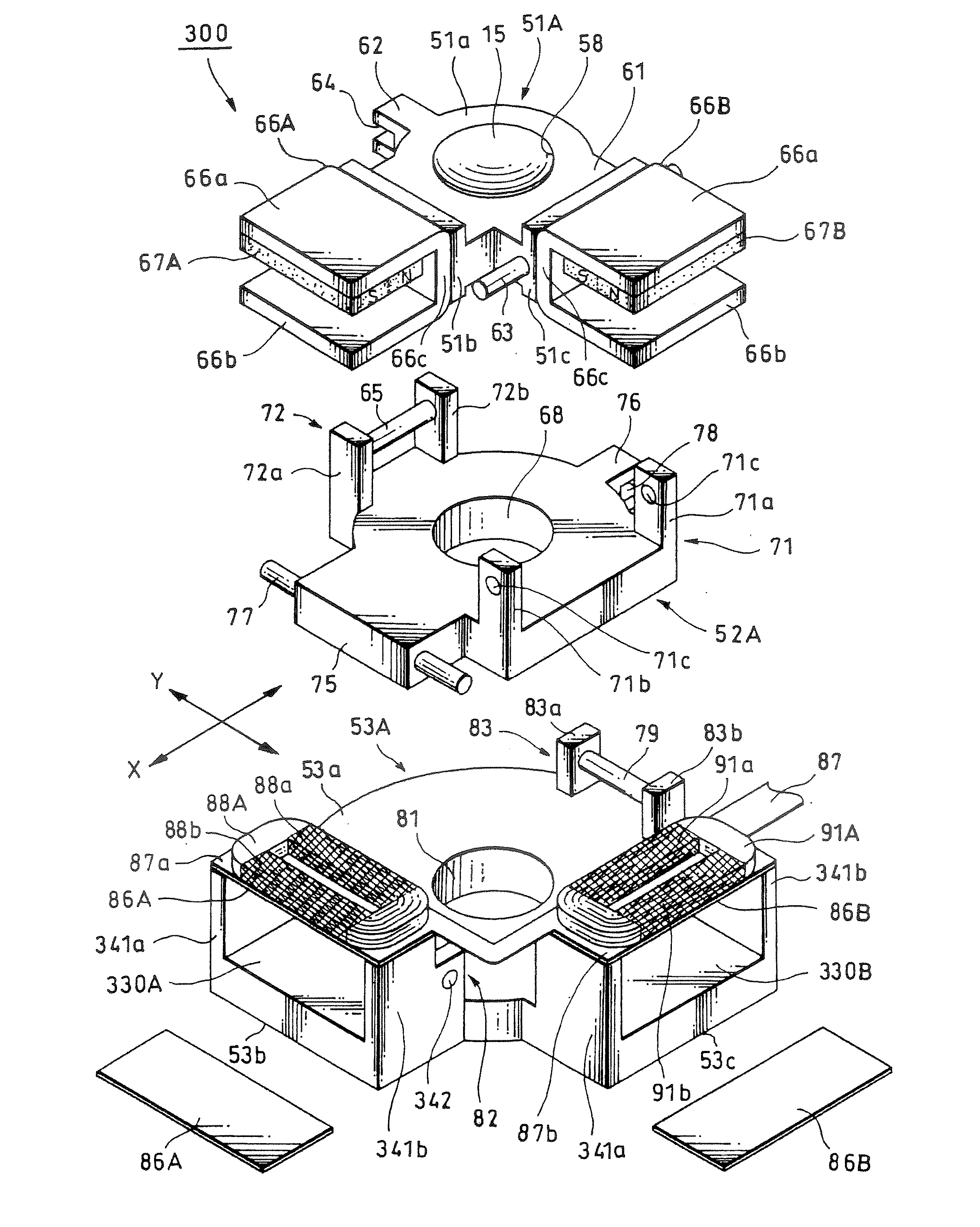
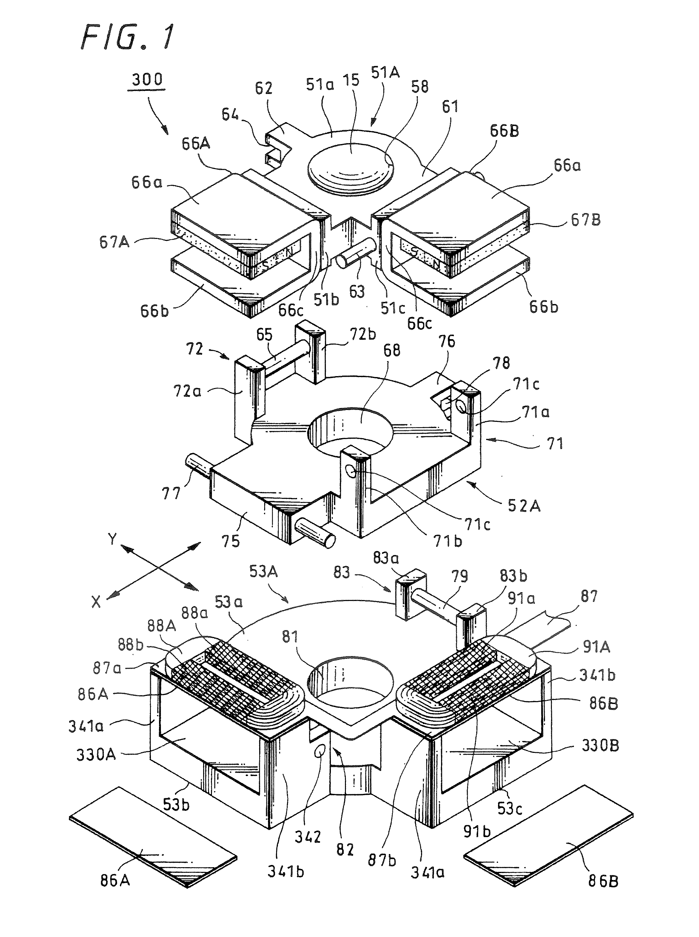
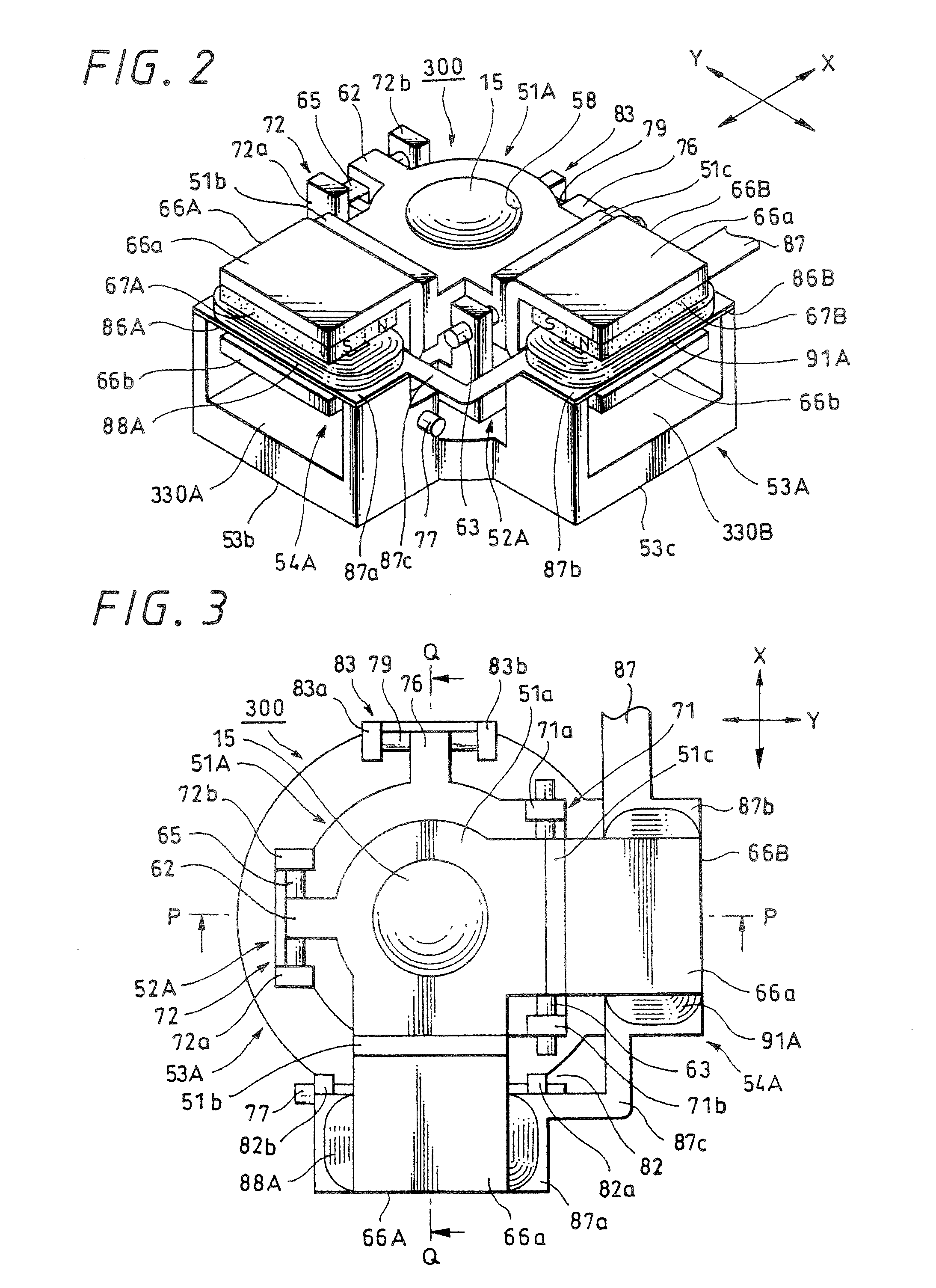
[0044] Further, FIGS. 10 to 12 explain a lens device according to the present invention: FIG. 10 is an explanatory diagram of a lens system; FIGS. 11A and 11B are a front view and a left side view of a lens device including an image stabilizer of a moving magnet system, respectively; and similarly, FIGS. 12A and 12B are a plan view and a perspective view respectively. FIG. 13 is a perspective view of a digital still camera representing a first example of an imager apparatus according to an embodiment of the present invention, as seen from the front side; and similarly FIG. 14 is a perspective view of a digital still camera, as seen from the rear side. FIG. 15 is a block diagram for explaining the concept of the control by an image stabilizer according to an embodiment of the present invention; FIG. 16 is a block diagram showing a first practice example of the schematic configuration of an imager apparatus according to an embodiment of the present invention; and similarly FIG. 17 is ...

second embodiment

[0136]FIG. 17 is a block diagram showing the schematic configuration of a digital still camera provided with an image stabilizer 300 having the above-described structure and functions. This digital still camera 200A includes a lens device 1, a video recording / reproducing circuit unit 160, an internal memory 161, a video signal processing unit 162, a display apparatus 163, an external memory 164, a correcting lens control unit 165 and the like. The lens device 1 has an image stabilizer 300. The video recording / reproducing circuit unit 160 plays a central role in a control device. The internal memory 161 has a program memory, data memory, other RAM / ROM or the like for driving the video recording / reproducing circuit unit 160. The video signal processing unit 162 processes a captured image or the like into a predetermined signal. The display apparatus 163 displays a captured image or the like. The external memory 164 enlarges storage capacity. The correcting lens control unit 165 drives...


PUM


Abstract

An image stabilizer includes a driver having a coil and magnet, where a correcting lens on a moving frame is moved by the driver in a first direction perpendicular to an optical axis of a lens system and in a second direction perpendicular to the first direction and optical axis, and an optical axis of the correcting lens corresponds with the optical axis of the lens system. The coil and magnet are fixed to the moving frame and a supporting frame; the driver includes first and second coils for moving the correcting lens in the first and second directions, and a magnet applying magnetic force to those coils; and thrust generated from the first and second coils are directed in the first and second directions, each forming an angle of approximately 45° with a line connecting the optical axis of the correcting lens and the center of a lens barrel.

Description

CROSS REFERENCES TO RELATED APPLICATIONS [0001] The present invention contains subject manner related to Japanese Patent Application JP 2005-355248 filed in the Japanese Patent Office on Dec. 8, 2005, the entire contents of which being incorporated herein by reference. BACKGROUND OF THE INVENTION [0002] 1. Field of the Invention [0003] The present invention relates to an image stabilizer which stabilizes image blurred by vibration or the like at the time of shooting; a lens device which has the image stabilizer; and an imager apparatus such as a digital still camera or video camera, incorporating the lens device. [0004] 2. Description of the Related Art [0005] In recent years, performance of an imager apparatus such as a digital still camera and a video camera has been improved remarkably, and it became possible for anyone to easily shoot still pictures and moving pictures with high image quality and with high efficiency. Improved efficiency of such an imager apparatus owes to high ...

Claims


Application Information

Patent Timeline
IPC IPC(8): G03B17/00
CPCG02B7/023G02B27/646G03B5/04G03B17/12H02K41/0356G03B2205/0015G03B2205/0069
Inventor TAKAHASHI, TATSUYUKIMAEDA, IPPEI
Owner SONY CORP
Why Eureka
Try Eureka