Fixed cellular terminal - wireless loop system

a wireless loop system and fixed cellular terminal technology, applied in the direction of wireless commuication services, network topologies, electrical appliances, etc., can solve the problems of limited to one cellular network at a time, designed to provide features such as personal data storage, short message services (sms, conventional fcts typically do not include service features), etc., to overcome drawbacks and shortcomings, increase functional capabilities, and flexibility

Inactive Publication Date: 2007-06-14
KING DENNIS +2
View PDF20 Cites 20 Cited by
  • Summary
  • Abstract
  • Description
  • Claims
  • Application Information

AI Technical Summary

Benefits of technology

[0011] The present invention overcomes the drawbacks and shortcomings of conventional fixed cellular telephone devices. The present invention is a fixed cellular terminal or Wireless Local Loop (WLL) with a plurality of cellular network circuits or cellular transceiver cartridges and standard telephone wire lines. The present invention is designed to provide the user with greater flexibility resulting in increased functional capabilities and a least cost method to change service providers, change network platforms and to easily upgrade the FCT device. Conventional FCTs require the entire unit to be replaced in order to change or upgrade networks. The novelty of present invention's FCT device rests in the use of a plurality of removable and interchangeable cellular transceiver cartridges. Each of the transceiver cartridges contains a cellular transceiver and essential control circuitry. The FCT has a main circuit board configured with circuitry and firmware designed to allow access and control of the cellular transceiver cartridge control circuitry, provide power to the transceiver cartridge and facilitate antenna connections. The transceiver module is preferably installed in a protective plastic casing designed to be inserted into a base interface unit of the FCT, wherein terminals enter a socket, which provides a connection to the main circuit board of the base interface unit.
[0012] Some of the primary features of present invention are: the device can be used with any combination of a plurality of transceiver cartridges and a plurality of telephone service lines; the device can be used on a variety of network platforms or service providers at the same time; the device provides a least cost upgrade method by requiring only the transceiver cartridge to be replaced; and, the FCT when installed in an optional wall mount bracket will provide a fail safe (power off) connection to a standard wire line telephone service hard wired between building telephone service entrance and building telephone wiring.

Problems solved by technology

FCT, as a rule, are not designed to provide features such as personal data storage, short message service (SMS) or gaming like many mobile cellular devices.
Further, conventional FCTs typically do not include service features such as voice mail, call waiting and call forwarding.
A deficiency with conventional FCTs is that they are limited to one cellular network at a time.
Further, conventional FCTs lack the ability to operate with multiple cellular networks and platforms simultaneously.
A further deficiency inherent with conventional FCTs is the inability to easily upgrade as cellular network technology upgrades.
Still an additional drawback of conventional FCTs is that while conventional FCTs can select between the least cost of the installed cellular network and the public switched telephone network (landline), conventional FCTs are limited to the cellular network installed.
If a different cellular network has cheaper rates, conventional FCTs cannot access them.
Another deficiency with conventional FCTs is their limited ability to conduct data transmissions.
Since conventional FCTs have only one cellular network multi-tasking ability is limited.
For example, conventional FCTs operating on a network that does not have high data capability can not take advantage of a network capable of high data rates without changing networks or devices.

Method used


Image

  • Fixed cellular terminal - wireless loop system
  • Fixed cellular terminal - wireless loop system
  • Fixed cellular terminal - wireless loop system

Examples


Embodiment Construction

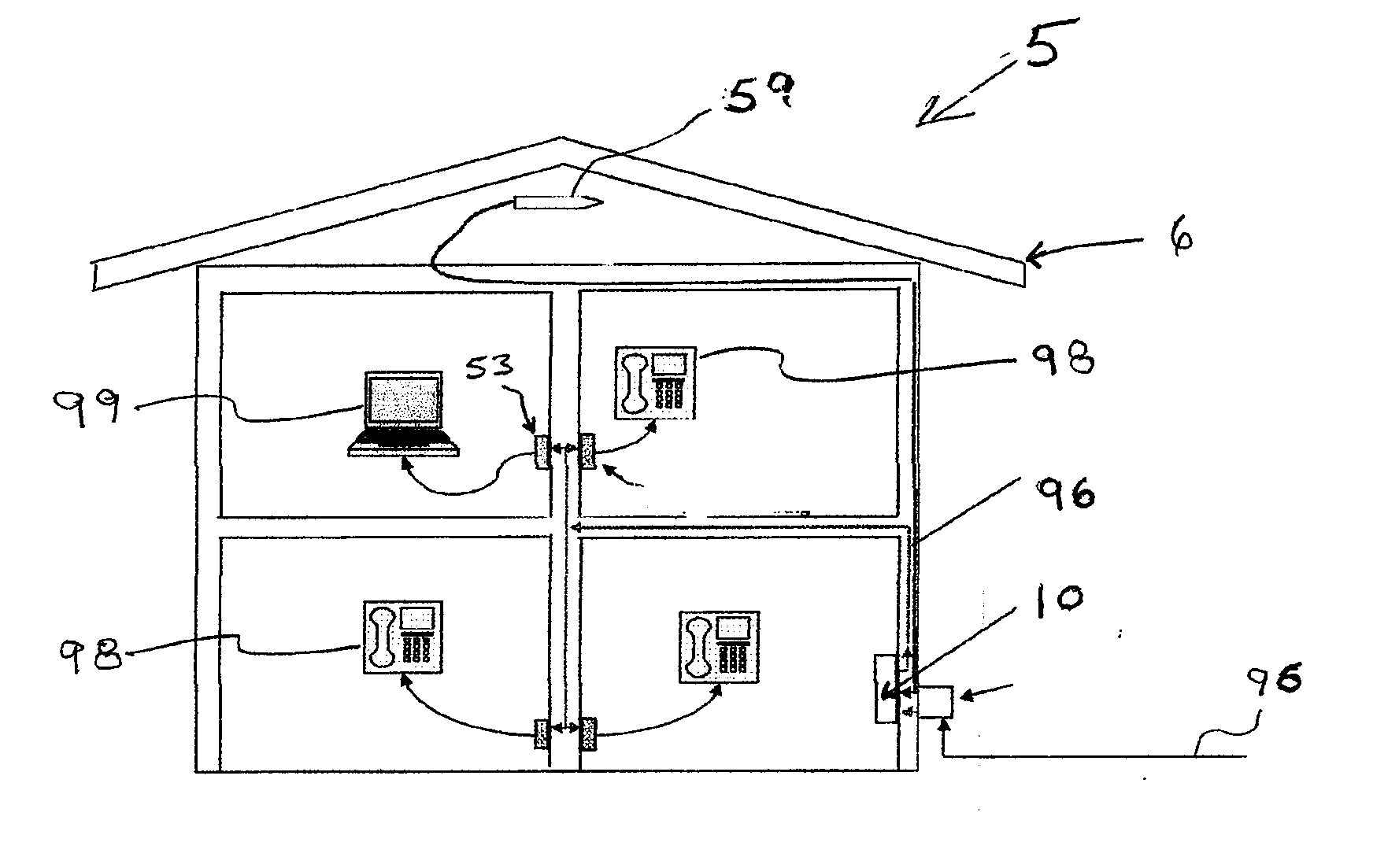
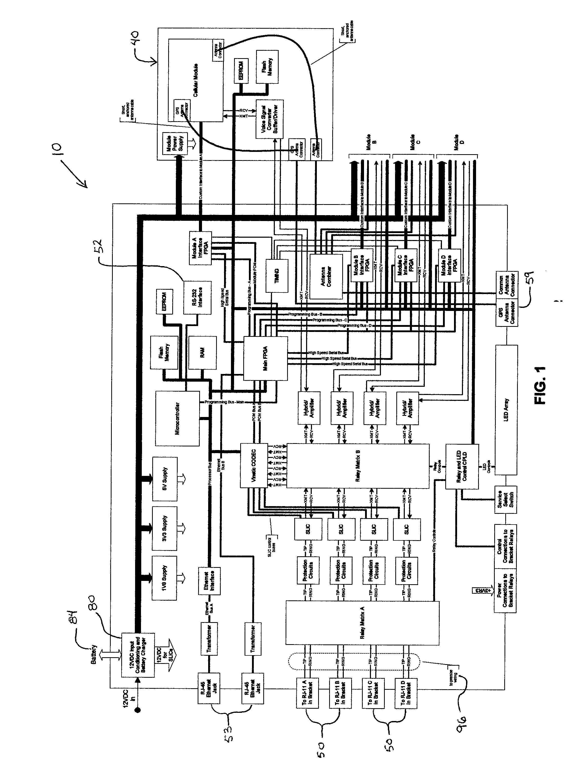
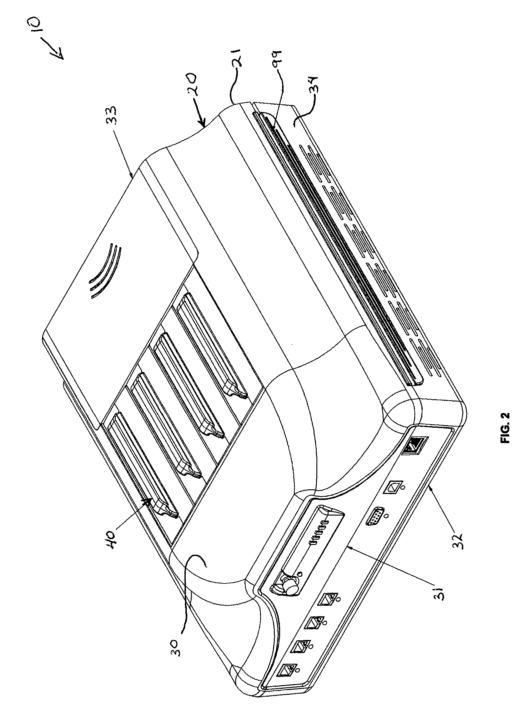
[0037]FIG. 1 is a block diagram of an exemplary embodiment of a fixed cellular terminal (FCT) made in accordance with the present invention showing the major components of the device 10 comprising: a base unit 20 and a plurality of transceiver cartridges 40. The device 10, when in use is connected to a public switched telephone network (PSTN) connection 96; and, at least one telephone 98 and is a system 5, as shown in FIGS. 14 and 15.

[0038] The transceiver cartridges 40 are a module type that are inserted into the base unit 20. The cartridges 40 make connections to a variety of cellular networks depending on the cellular provider and will be discussed below in further detail. The PSTN 96 is a standard landline or Plain Old Telephone Service (POTS) installed in most buildings connected to the base unit 20.

[0039] The telephone or handset 98 is a common telephone as used in homes or offices. The telephone 98 is connected to the base unit 20 through a RJ-11 phone jack 50. It should be...


PUM


Abstract

A device that provides a gateway between a public switching telephone network and a gateway device comprises a controller interface including telephony circuitry, power circuitry, and a master cellular phone circuit. The controller is connected to at least one public switching network. The controller interface further includes a plurality of cartridge slots connected to the telephony circuitry and the master cellular phone circuitry, wherein the telephony circuitry links the master cellular phone circuitry to the public switching telephone network. The device further includes a plurality of transceiver cartridges removeably connected to the cartridge slots of the controller interface. The transceiver cartridges are operably configured to wirelessly link the master cellular phone circuitry to the cellular networks. Additionally, the controller interface circuitry is operably configured to switch between land line telephone network and the plurality of cellular networks based on preset conditions.

Description

CROSS REFERENCE TO RELATED APPLICATION [0001] This application is a nonprovisional application of U.S. Application No. 60 / 725,735, filed on Oct. 11, 2005, which is incorporated, in its entirety, herein by reference.BACKGROUND OF THE INVENTION [0002] 1. Field of Invention [0003] The present invention relates to fixed cellular terminal device. [0004] 2. Description of Related Art [0005] A fixed cellular terminal (FCT) is an apparatus designed to be used in a fixed location and allows the user the ability to use a standard telephone handset, fax machine or personal computer (PC) to transmit voice and data over a cellular network as an alternative or back-up to a standard wire line telephone service. FCTs provide an interface between the user's analog devices (standard home or office phone) and a cellular transceiver. When the FCT is connected to the analog devices and the cellular transceiver a Wireless Local Loop (WLL) is created. The interface emulates the functions of a standard wir...

Claims


Application Information

Patent Timeline
Patent Type & Authority Applications(United States)
IPC IPC(8): H04Q7/20H04W8/18H04W84/14H04W88/06
CPCH04W8/18H04W84/14H04W88/06H04W88/16
Inventor KING, DENNISROSEN, MARK N.LEWALSKI, WOJCIECH B.
Owner KING DENNIS
Why Eureka
Try Eureka