Surface guided knee replacement

a knee joint and surface guided technology, applied in the field of knee prosthesis, can solve the problems of still needed rotational laxity, and achieve the effects of high flexion, high flexion, and large contact area

Active Publication Date: 2007-06-14
NEW YORK UNIV
View PDF99 Cites 205 Cited by
  • Summary
  • Abstract
  • Description
  • Claims
  • Application Information

AI Technical Summary

Benefits of technology

[0012] A number of characteristics which are ideally included in the configuration are as follows. The posterior displacement is small from approximately 0-45 degrees flexion, which has the advantage that a large area of contact can be maintained in that major functional range. The total posterior translation should be approximately 10-15 mm, but where the posterior limit is not too close to the posterior edge of the tibial component. The reason is that some rotational laxity is still needed in high flexion and it is undesirable if the femoral condyles ride on or over the very posterior edge of the tibial component. The patella mechanism is an important consideration in an artificial knee.
[0013] In the anatomic knee, past about 110 degrees flexion, the contact between the patella and the digital end of the femur splits into two separate areas on the lateral and medial condyles. Most artificial knees cause the same scheme, especially when intercondylar cams are used. However, it would be an advantage is contact in high flexion was over the entire width of the patella, which would considerably reduce the stresses on the artificial patella and the remaining bone. Continuous contact is possible with a surface guided design or configuration.

Problems solved by technology

The reason is that some rotational laxity is still needed in high flexion and it is undesirable if the femoral condyles ride on or over the very posterior edge of the tibial component.

Method used


Image

  • Surface guided knee replacement
  • Surface guided knee replacement
  • Surface guided knee replacement

Examples


Embodiment Construction

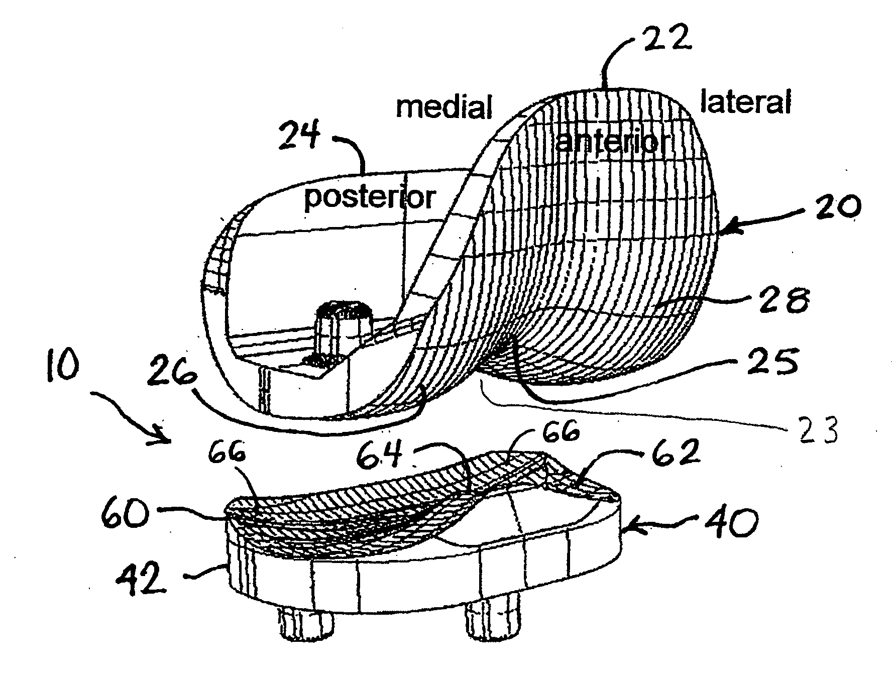
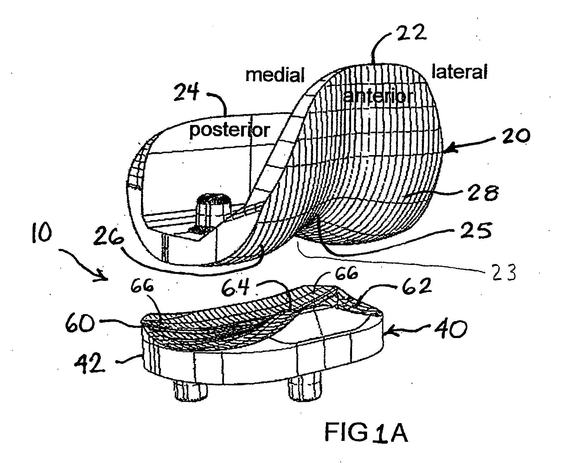
[0038] Referring to FIG. 1A, a surface guided knee replacement 10 is shown in a position of approximately zero degrees flexion and includes a femoral component 20 and a tibial component 40. Femoral component 20 connects to a shaped distal end of a femur. In the embodiment shown, the tibial component 40 is one-piece, but can also be a bearing component fixed into a tibial tray or baseplate. The tibial component 40 connects to a shaped proximal end of a tibia and includes a bearing surface 62 that receives and guides the flexion of femoral component 20.

[0039] Femoral component 20 has a proximal-anterior portion 22 and an opposed proximal-posterior portion 24 that define an arcuate curve. Component 20 includes an intercondylar surface 25 that connects a medial condyle 26 and a lateral condyle 28. Intercondylar surface or patella groove 25 defines a recess or notch that has a depth that progressively diminishes from the proximal-anterior portion 22 to the proximal-posterior portion 24....


PUM


Abstract

An artificial knee joint that includes a femoral component with a specially shaped bearing surface and a tibial component, whose surface interacts with the femoral surfaces. The interaction provides for the required motion and stability characteristics. The interaction between the femoral and tibial surfaces is such that as the knee is flexed to maximum, the femoral component moves posteriorly on the tibial surface, by an amount similar to that in the anatomic knee. This is accomplished primarily by the depth and width of the femoral trochlea diminishing as the femoral component is flexed from zero to maximum, together with a ramp on the center of the tibial surface. The opposite motion, roll forward of the femur from a fully flexed to a more extended position, is accomplished by varying the outward radii of the lateral and medial femoral bearing surfaces, together with a ramp on the postero-lateral and postero-medial regions of the tibial surfaces. A variation of this is to generate a tibial surface which provides for a progressive internal rotation of the tibia as flexion proceeds.

Description

FIELD OF THE INVENTION [0001] The present invention relates to knee prostheses and more specifically to surface guided total knee replacement prostheses. BACKGROUND OF THE INVENTION [0002] One of the major objectives of an artificial knee joint is to restore the mechanics of the anatomic knee. However the anatomic knee is complex, consisting of structures such as the articular surfaces, ligaments, and muscles, which cannot all be replicated by artificial parts at this time. This problem is mitigated by the fact that arthritis involves destruction of the condylar bearing surfaces and the menisci, while the remaining parts of the knee are largely intact and can still function. Hence, if an artificial knee joint provides a replacement for the bearing surfaces using metal and plastic materials, reasonably normal joint function can theoretically be achieved. This is the fundamental principal behind the large majority of the resurfacing types of knee joint that have been designed since ab...

Claims


Application Information

Patent Timeline
Patent Type & Authority Applications(United States)
IPC IPC(8): A61F2/38
CPCA61F2/3859
Inventor WALKER, PETER
Owner NEW YORK UNIV
Why Eureka
Try Eureka