Shaft drive for a power loom

a technology of power looms and shaft drives, which is applied in the direction of looms, dollies, textiles and papermaking, etc., can solve the problems of high cost of modulation gears and large structural volume of cams and modulation gears on the whole, and achieves low structural size and material use, considerable torque, and simple and cost-effective

Inactive Publication Date: 2007-06-21
GROZ BECKERT KG
View PDF36 Cites 8 Cited by
  • Summary
  • Abstract
  • Description
  • Claims
  • Application Information

AI Technical Summary

Benefits of technology

[0011] The eccentric toothed gearing represents a simple and cost-effective solution for achieving a heddle shaft movement that deviates considerably from the sinusoidal shape, in particular if the heddle shaft dwells for a longer period in the upper or lower extreme position (dead center position) than is the case for the approximately sinusoidal movement and must travel faster through the transitional region between the upper and lower dead center position than would be the case for a sinusoidal movement. The eccentric toothed gearing is thus capable of transmitting considerable torque, while the structural size and the material use are low. Thanks to modem production methods (CNC production), an eccentric toothed gearing can be produced in series and cost-effectively. Despite the longer dwell time in the dead center positions (extreme stroke positions) and despite the faster travel over the distance between both extreme stroke positions, the torque increases before and after the extreme stroke positions can be minimized. In the process, a polynomial to the seventh power is selected as the law of motion for the shaft, at least for one preferred embodiment, wherein the torque increase during the introduction and completion of the movement is soft.
[0012] In principle, this shaft drive is suitable for continuously operating heddle shafts (eccentric machines) as well as for heddle shafts that must be started and stopped (heddle machines), for example, for generating complicated weaving patterns. In that case, the gearing is provided with a coupling device, which in one operating position transmits the driving movement without problem and, in a second operating position, interrupts the transmission of the movement. By extending the dwell time for the shaft in the extreme stroke positions, a longer time interval and a larger angle region is provided there for engaging and disengaging the coupling device, wherein the engaging and disengaging occurs essentially without load and with a minimum torque as well as minimum rotational speed for the coupling elements. Load jolts and the coupling load are reduced and / or minimized.
[0013] The coupling arrangement of one preferred embodiment permits a pendulum movement of the power take-off, or generates such a movement, in case of an interruption of the drive movement. The pendulum movement on the one hand can be used to minimize the accelerations of the heddle shaft and, on the other hand, to create synchronous phases in which the coupling can softly engage or disengage.
[0015] The eccentric toothed gearing is preferably provided with spur wheels having a whole number ratio of the teeth, relative to each other. For a preferred embodiment, the number of teeth on the toothed gears is the same. As a result, a transmission ratio of 1:1 is obtained on the whole, meaning on the average, wherein this transmission ratio is above or below one at each rotational angle, in dependence on the respective rotational position of the toothed gears relative to each other. The toothed gears of one simple exemplary embodiment are elliptical in shape, wherein toothed gears of this type can be slightly counterbalanced and increase and / or reduce the transmission ratio twice during one rotation of the input shaft. A connected eccentric cam plate for the power take-off of the shaft drive can thus be delayed in both extreme positions. With this measure, the angle at which the shed is at a standstill can be increased, meaning more time is available for inserting the weft yarn into the shed.

Problems solved by technology

A modulation gear of this type is expensive.
In addition, it has turned out that the cams and the modulation gears on the whole require a relatively large structural volume.

Method used


Image

  • Shaft drive for a power loom
  • Shaft drive for a power loom
  • Shaft drive for a power loom

Examples


Embodiment Construction

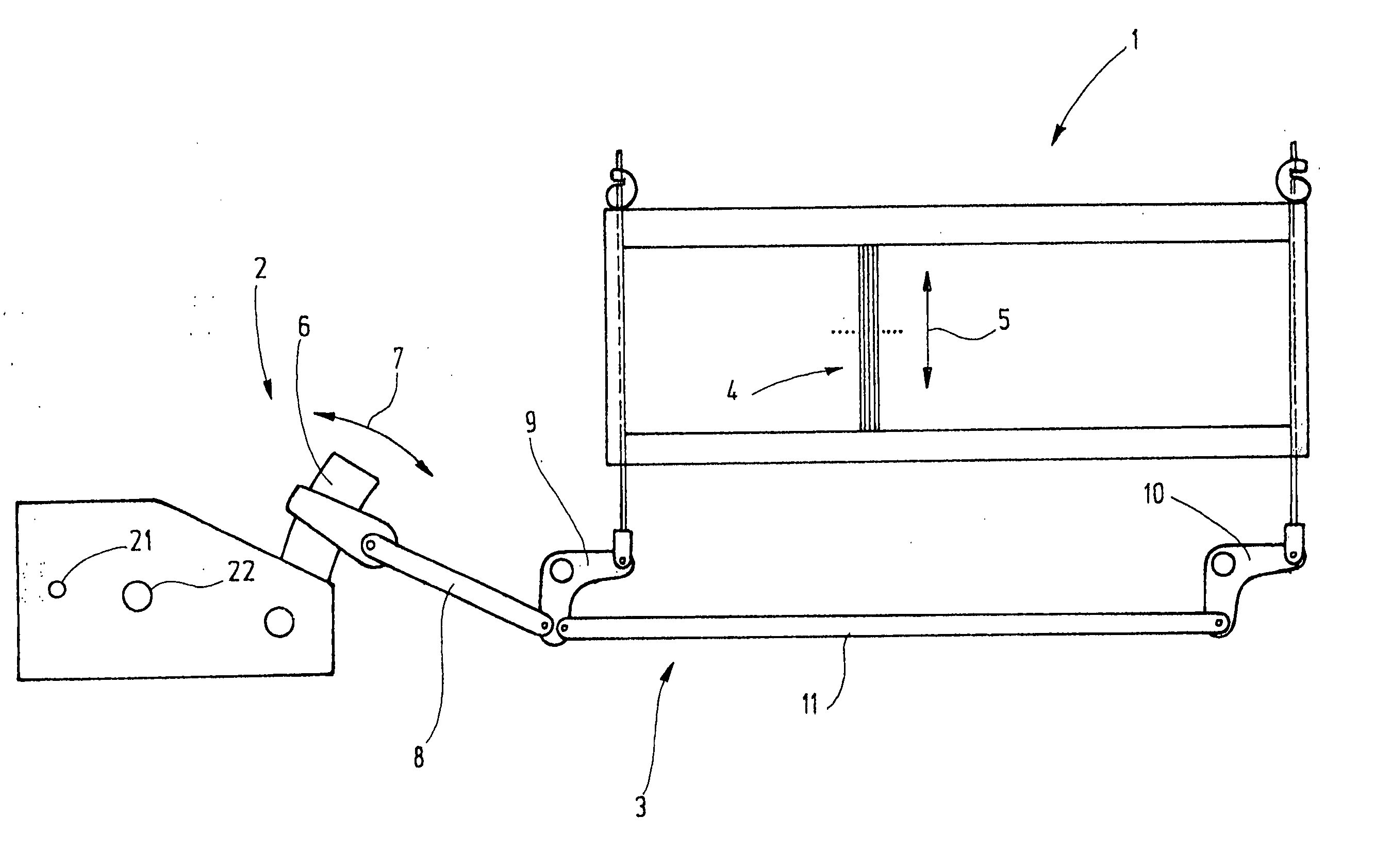
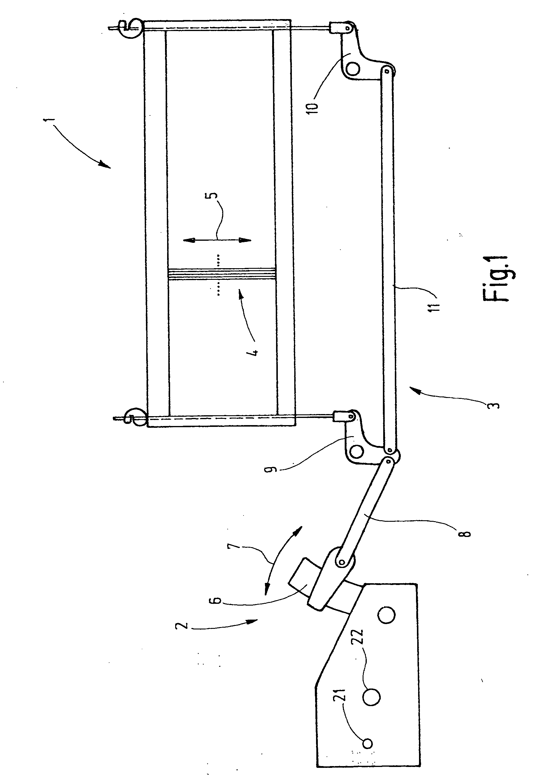
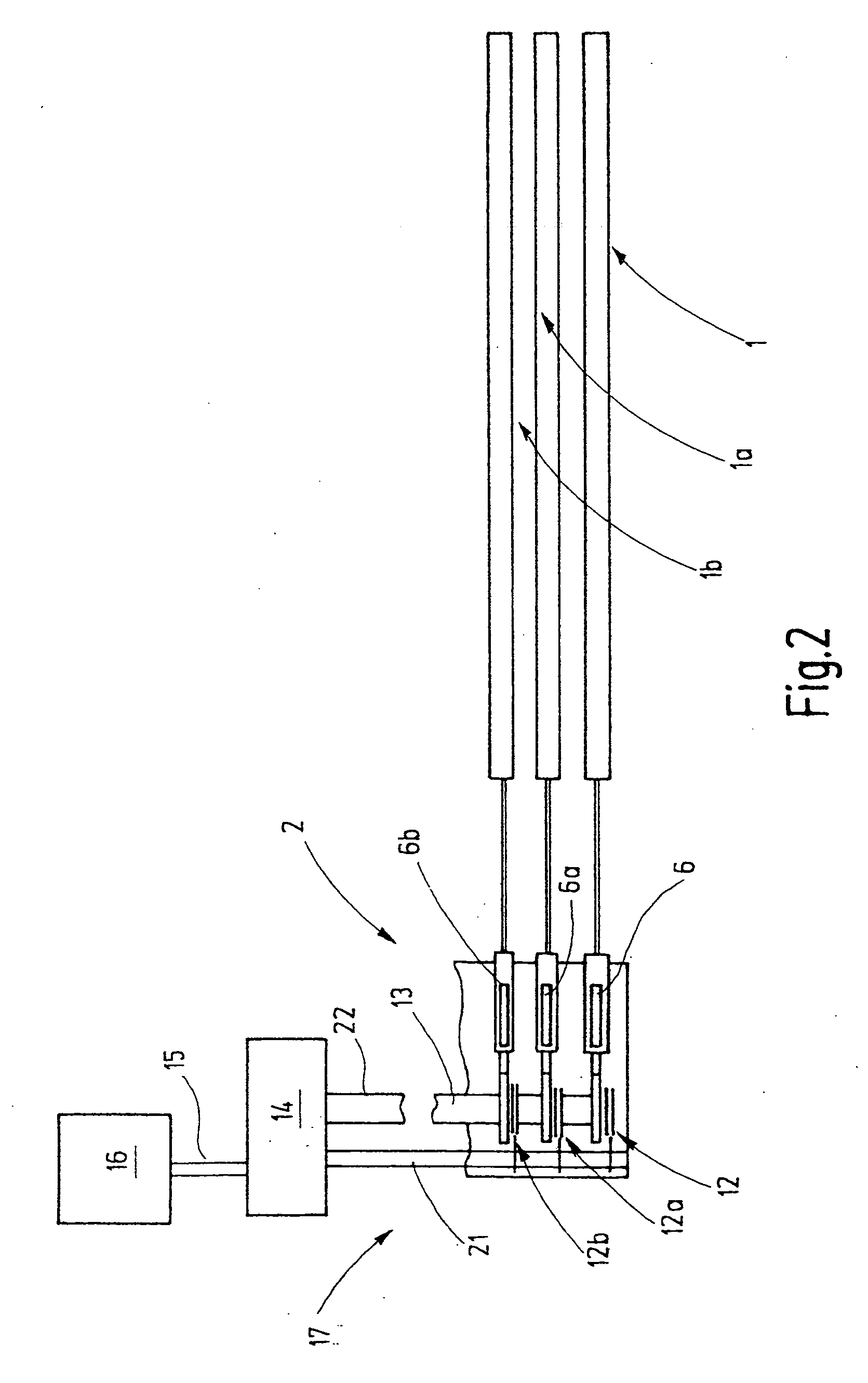
[0024]FIG. 1 illustrates a heddle shaft 1 with thereto assigned heddle machine ore dobby 2, which drives the shaft via a rod assembly, embodied as lever gear 3. FIG. 2 shows that additional heddle shafts 1a, 1b, etc. are provided parallel to the heddle shaft 1, wherein these shafts are also driven by the heddle machine 2. Insofar, this arrangement is a traditional arrangement. The heddle shafts, which function to drive heddles 4 up and down as indicated by arrow 5, are moved up and down by the lever gear 3. For this, the swinging movement (arrow 7), executed by a rocker 6 functioning as power take-off for the heddle machine 2 is converted by the lever gear 3 into the vertically directed shaft movement with the aid of a steering gear 8, an angle lever 9, 10, and a connecting rod 11.

[0025] As shown in FIG. 2, the heddle machine 2 is provided with rockers 6a, 6b as power take-off for driving the additional heddle shafts 1a, 1b. These rockers are driven by means of a shaft 13, via coup...


PUM


Abstract

The heddle shaft (1) according to the invention combines a traditional heddle machine (2) with an eccentric toothed gearing to purposely allow the heddle shaft (1) to dwell for longer periods of time in the upper and lower reversing region and to reduce any accelerations that occur. This permits an increase in the weaving speed and / or the weaving widths. For a particularly advantageous embodiment, a coupling device is additionally provided, which gives the heddle shaft (1) a pendulum movement with a stroke ranging from a few millimeters to centimeters during the idle phases, meaning when no sheds are formed. As a result of the pendulum movement of the heddle shaft (1) in the upper or lower reversing region, the acceleration loads on the heddle shaft (1) can be further reduced.

Description

CROSS REFERENCE TO RELATED APPLICATION [0001] This application claims the priority of German Patent Application No. 10 2005 059 911.7, filed on Dec. 15, 2005, the subject matter of which, in its entirety, is incorporated herein by reference. BACKGROUND OF THE INVENTION [0002] The invention relates to a shaft drive for a power loom, provided with one or several heddle shafts. [0003] Power looms are generally provided with several heddle shafts in the form of rectangular, vertically positioned frames. These heddle shafts accommodate heddles for guiding the on the whole horizontally extending warp threads, so as to move them vertically up and down for the shed forming. In the process, the heddle shafts normally execute an up and down swinging movement, generated by a so-called shaft drive and / or a heddle machine. The shaft drive is a gear for converting the rotational driving movement to a back and forth movement, wherein the shaft essentially follows a sinusoidal function. [0004] Star...

Claims


Application Information

Patent Timeline
Patent Type & Authority Applications(United States)
IPC IPC(8): D03C13/00
CPCD03C1/14D03C1/146D03C13/00D03D51/16D03C1/148
Inventor POHL, GERHARD
Owner GROZ BECKERT KG
Why Eureka
Try Eureka