Hand-held power tool with ratchet percussion mechanism

a technology of percussion mechanism and hand-held power tools, which is applied in the direction of percussive tools, manufacturing tools, drilling pipes, etc., can solve the problems of affecting energy loss, deformation of the housing, and affecting the operation efficiency, so as to increase the operation efficiency and stability

Inactive Publication Date: 2007-06-21
HILTI AG
View PDF12 Cites 20 Cited by
  • Summary
  • Abstract
  • Description
  • Claims
  • Application Information

AI Technical Summary

Benefits of technology

[0010] It is an object of the present invention to eliminate the disadvantages mentioned above in a hand-held power tool of a shell-type construction and to increase operational efficiency and stability.
[0011] This and other objects of the present invention, which will become apparent hereinafter, are achieved by providing a power tool in which the supporting means are formed so as to extend circumferentially at an inner surface of an outer shell of the main housing, and the supporting body directly contacts the supporting means. In this way, a direct flow of force is achieved from the main housing to the supporting body with the toothed rim held thereon and which is fixed with respect to the housing. Thereby, the impact energy loss can be appreciably reduced, and the operational efficiency of the hand-held power tool can be increased. The circumferentially arranged supporting means provides for a particularly stable support in the operational direction. The circumferential arrangement can be circumferentially continuous or circumferentially discontinuous.
[0012] The supporting body advantageously forms a radial contact surface which contacts the outer shell circumferentially in radial direction. In this way, the supporting body supports the main housing on the inner side and accordingly imparts a greater stability, particularly with respect to external loads on the main housing acting transverse to the operational axis.

Problems solved by technology

Due to relative movements of the two housing parts caused by deformations, impact energy losses occur particularly between the main housing and the portion of the inner housing that is supported at a relatively large distance from the latter.
This can impair operational efficiency particularly in comparison with tools of cup-type construction which also have main housing portions that extend transverse to the operational axis and support the supporting body axially form behind.
Also, a tool of the kind mentioned above which has a shell-type construction, usually a plastic housing, in order to reduce weight, is relatively susceptible to forces acting on the housing from the outside transverse to the operational axis.
For example, attaching a side handle with a clamping band that is securely clamped around the housing, can lead to a deformation of the housing.
These deformations can lead, in turn, to malfunction or complete blocking of components of the tool such as the gear unit, a torque clutch, or an on / off circuit of the percussion device, for example.

Method used


Image

  • Hand-held power tool with ratchet percussion mechanism
  • Hand-held power tool with ratchet percussion mechanism
  • Hand-held power tool with ratchet percussion mechanism

Examples


Embodiment Construction

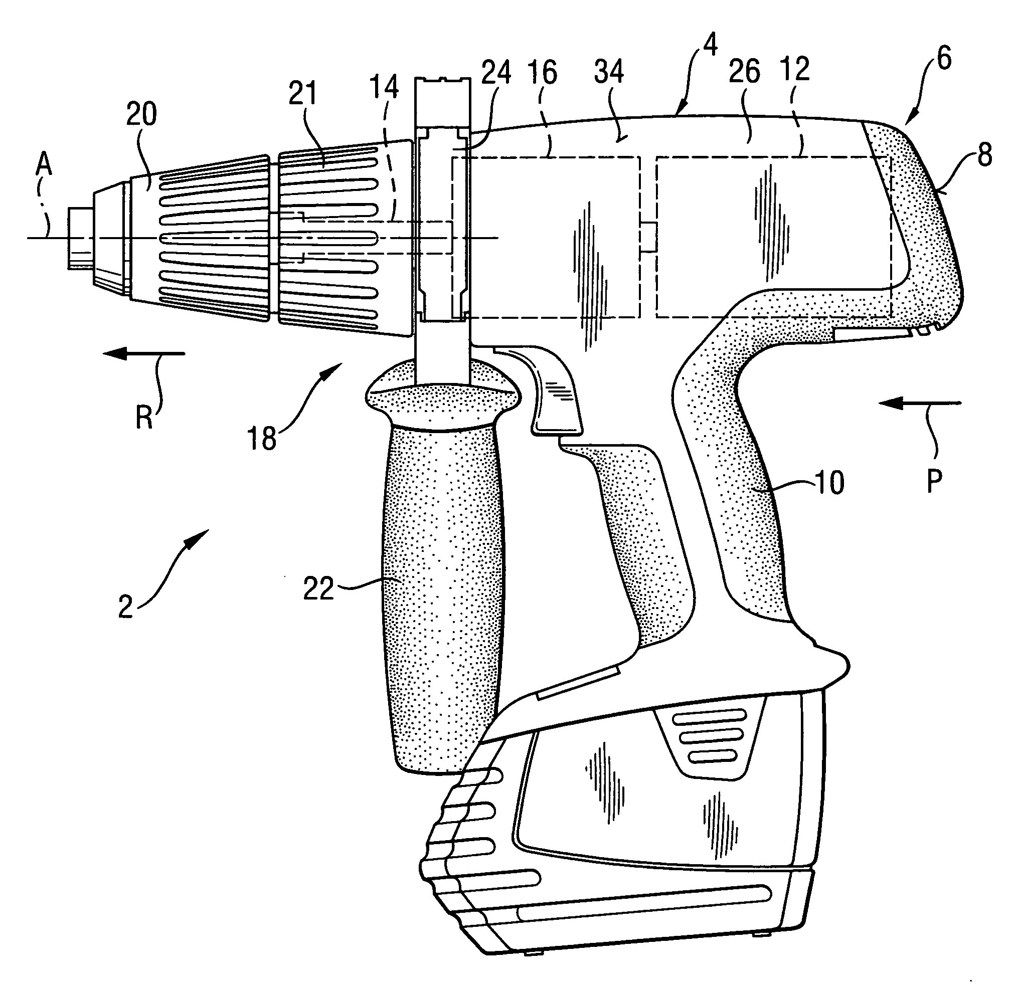
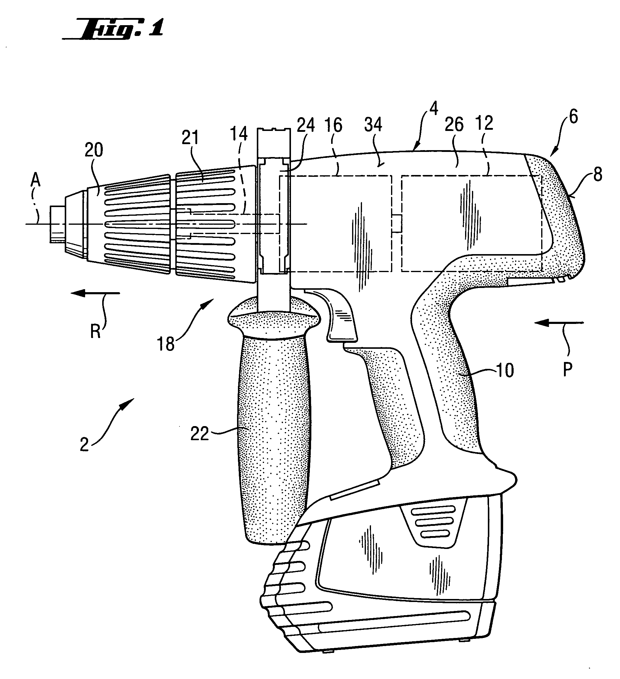
[0026]FIG. 1 shows a hand-held power tool 2 in the form of a battery-operated screw-driving power tool with an axial impact function. The screw-driving power tool has a main housing 4 of shell-type construction which has two parts and which forms a contact pressing surface 8 at its rear end 6 and from which a pistol-like handle 10 projects laterally. A motor 12 is accommodated in the main housing 4. The motor 12 rotates a tool spindle 14 around an operational axis A by means of a gear unit 16.

[0027] The tool spindle 14 projects in operational direction R from a working tool-end side 18 of the main housing 14 and is connected at its free end to a tool holder 20 in the form of a chuck for a joint rotation therewith. The tool spindle 14 projects through an adjusting sleeve 21 which is supported for rotation between the main housing 4 and the tool holder 20 for adjusting a maximum torque.

[0028] Further, a side handle 22, which is fixedly clamped to the main housing 4 by a clamping ban...


PUM


Abstract

An electric hand-held power tool (2) has a main housing (4) of a shell-type construction a tool spindle (14) projecting from the main housing (4) at a working tool-side end (18) of the housing and which can be rotated around a operational axis (A) by a motor (12) and a gear unit (16) which are accommodated in the main housing (4), with an axial percussion movements being applied to the tool spindle (14) by a ratchet percussion mechanism (38) having a toothed rim (43), which is fixed with respect to the housing and which is connected to a supporting body (44) that is supported in the main housing (4), the toothed rim (43) cooperating with a toothed rim (41) which is movable so as to be coupled with the tool spindle (14) for joint rotation therewith, and the supporting body (44) being supported by a supporting element (58) in a direction remote from the working tool-side end (18) of the housing, with the supporting element (58) being formed in a circumferentially extending manner at an inner surface (56) of an outer shell (34) of the main housing (4), and the supporting body (44) directly contacting the supporting element (58).

Description

BACKGROUND OF THE INVENTION [0001] 1. Field of the Invention [0002] The invention relates to an electric hand-held power tool including a main housing, formed particularly of a plastic material and having a shell-type construction, and a tool spindle which can be connected to a tool holder for joint rotation therewith and which projects from the main housing at its working tool-side end. The tool spindle can be rotated around a operational axis by a motor and a gear unit which are accommodated in the main housing. In addition, axial percussion movements can be applied to the tool spindle along the operational axis by a ratchet percussion mechanism. For this purpose, the ratchet percussion mechanism has a toothed rim which is fixed with respect to the housing and which is connected to a supporting body that is supported in the main housing. The toothed rim cooperates with a toothed rim which is movable so as to be coupled with the tool spindle for joint rotation therewith, and the su...

Claims


Application Information

Patent Timeline
Patent Type & Authority Applications(United States)
IPC IPC(8): E21B19/16
CPCB25B21/023B25D11/106B25D16/00B25D17/00B25D2250/121B25D2250/245
Inventor SPIELMANN, DAVID
Owner HILTI AG
Why Eureka
Try Eureka