

Integrated heavy oil upgrading process and in-line hydrofinishing process
Active Publication Date: 2007-06-21
CHEVROU USA INC
View PDF12 Cites 64 Cited by
- Summary
- Abstract
- Description
- Claims
- Application Information
AI Technical Summary
Benefits of technology
[0009] U.S. Ser. No. 10 / 938,269 is directed to a process for upgrading heavy oils using a slurry composition. The slurry composition is prepared by a series of steps, involving mixing a Group VIB metal oxide and aqueous ammonia to form an aqueous mixture, and sulfiding the mixture to form a slurry. The slurry is then promoted with a Group VIII metal. Subsequent steps involve mixing the slurry with a hydrocarbon oil and combining the resulting mixture with hydrogen gas and a second hydrocarbon oil having a lower viscosity than the first oil. An active catalyst composition is thereby formed.
Problems solved by technology
Some of these products require further processing due to their high nitrogen, high sulfur and high aromatics content, as well as low API.
Method used
View moreImage
Smart ImageViewing Examples

Examples
example
In-Line Hydrofinishing Performance
[0033]
Feed fromslurryFull RangeJet Fuel CuthydrocrackerProduct fromfromDiesel CuttoHydro-Hydro-fromHydrofinisherfinisherfinisherHydrofinisherAPI34.838.9Sulfur,330063wppmNitrogen,25002368wppmSmoke19Point,mmCetane44Index
[0034] It is apparent from the Table above that hydrofinishing of the product of slurry hydrocracking provides dramatic reduction of sulfur and nitrogen content. In both full range product and in individual product cuts, such as jet fuel and diesel.
Login to View More PUM
 Abstract
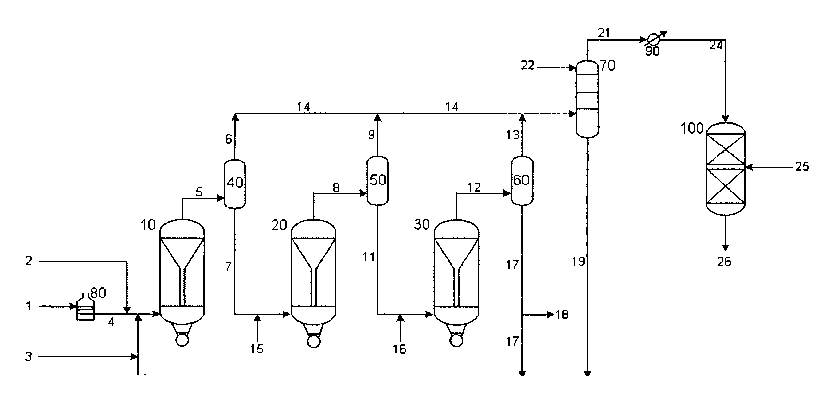
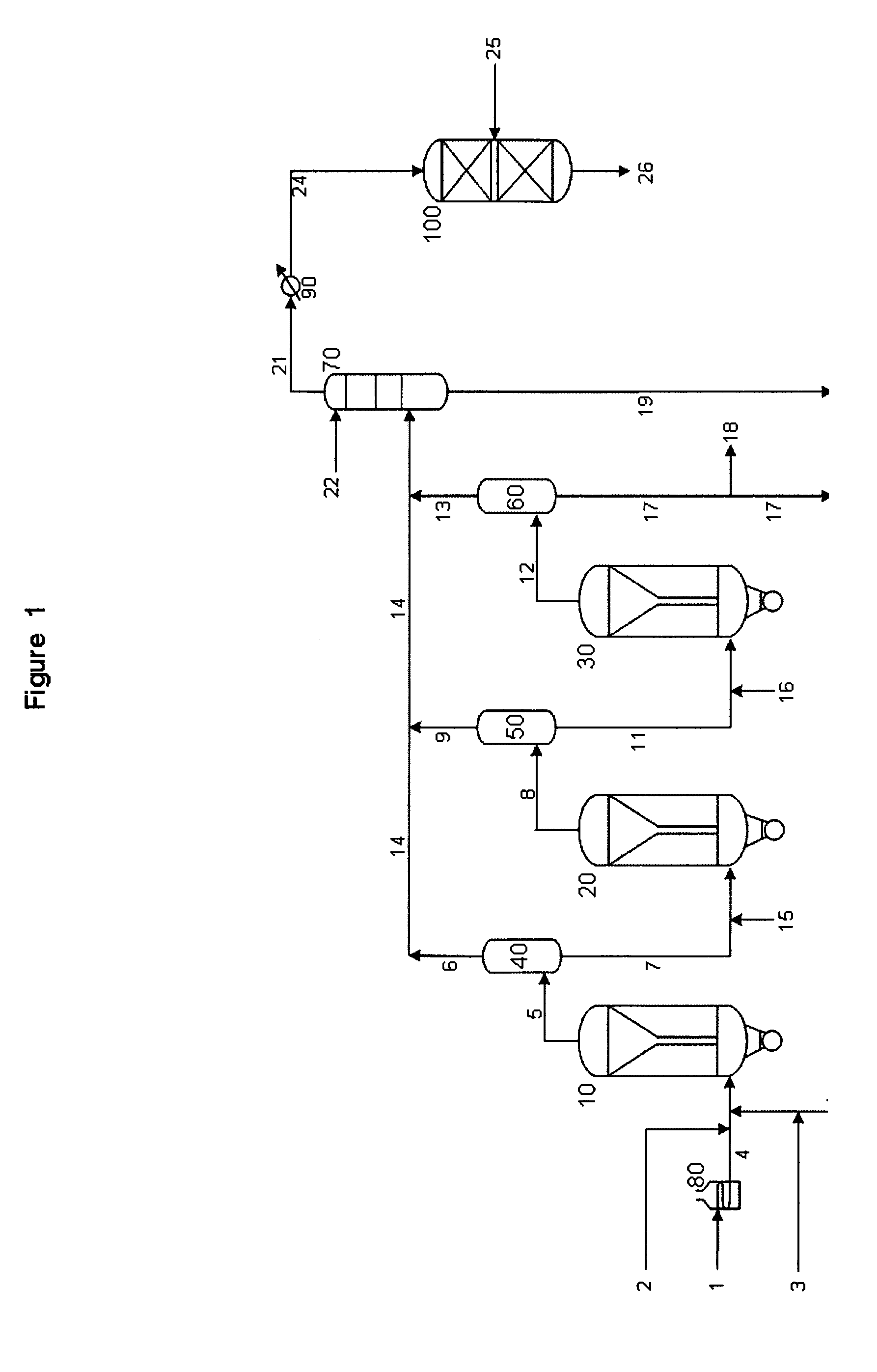
A new residuum full hydroconversion slurry reactor system has been developed that allows the catalyst, unconverted oil and converted oil to circulate in a continuous mixture throughout an entire reactor with no confinement of the mixture. The mixture is partially separated in between the reactors to remove only the converted oil while permitting the unconverted oil and the slurry catalyst to continue on into the next sequential reactor where a portion of the unconverted oil is converted to lower boiling point hydrocarbons, once again creating a mixture of unconverted oil, converted oil, and slurry catalyst. Further hydroprocessing may occur in additional reactors, fully converting the oil. The oil may alternately be partially converted, leaving a highly concentrated catalyst in unconverted oil which can be recycled directly to the first reactor. Fully converted oil is subsequently hydrofinished for the nearly complete removal of hetoroatoms such as sulfur and nitrogen.
Description
[0001] This application is a Continuation-In-Part of co-pending application Ser. No. 11 / 305,377, Filed Dec. 16, 2005 and Ser. No. 11 / 305,378, filed on Dec. 16, 2005.FIELD OF THE INVENTION [0002] The instant invention relates to a process for upgrading heavy oils using a slurry catalyst composition, followed by hydrofinishing. BACKGROUND OF THE INVENTION [0003] There is an increased interest at this time in the processing of heavy oils, due to larger worldwide demand for petroleum products. Canada and Venezuela are sources of heavy oils. Processes which result in complete conversion of heavy oil feeds to useful products are of particular interest. [0004] The following patents, which are incorporated by reference, are directed to the preparation of highly active slurry catalyst compositions and their use in processes for upgrading heavy oil: [0005] U.S. Ser. No. 10 / 938,202 is directed to the preparation of a catalyst composition suitable for the hydroconversion of heavy oils. The cata...
Claims
Login to View More Application Information
Patent Timeline
 IPC IPC(8): C10G45/00
CPCC10G65/02C10G65/04C10G65/12C10G2300/4018C10G2300/1022C10G2300/4081C10G2300/1074C10G2300/1077C10G2300/202C10G2300/302C10G2300/107C10G47/14C10G47/26C10G65/10
InventorFARSHID, DARUSHREYNOLDS, BRUCE
OwnerCHEVROU USA INC