

Devices and methods for microfluidic chromatography
a microfluidic chromatography and microfluidic technology, applied in the direction of filtration separation, separation processes, instruments, etc., can solve the problems of inconvenient chromatography devices or methods, inability to achieve the flow rate desirable for timely separation, etc., to achieve rapid separation of analytes, reduce sample volume and contamination, and reduce dead volume
- Summary
- Abstract
- Description
- Claims
- Application Information
AI Technical Summary
Benefits of technology
Problems solved by technology
Method used
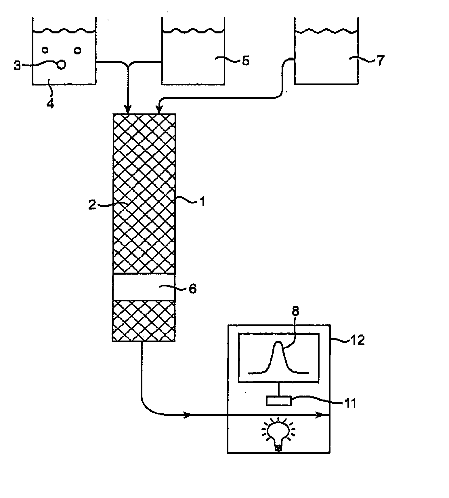
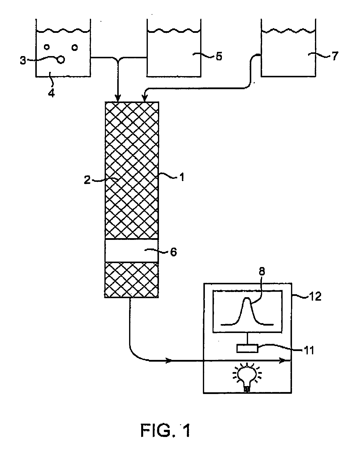
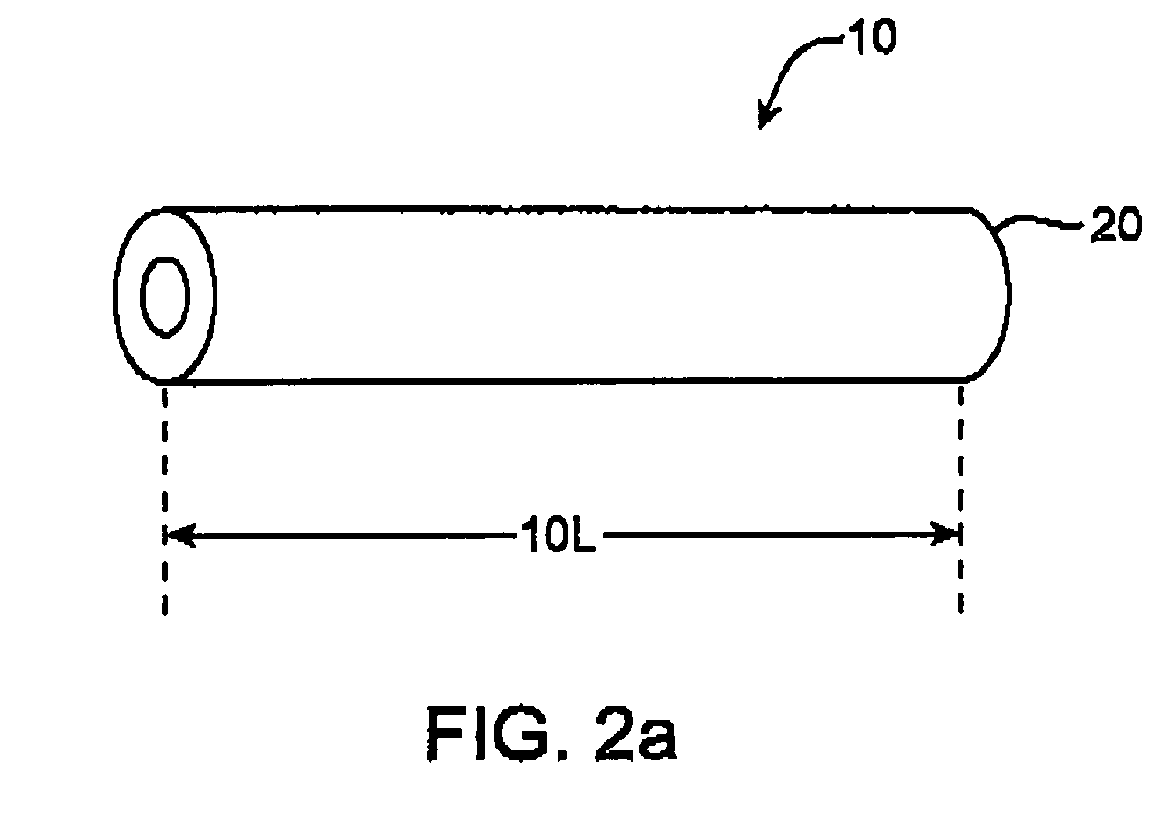
Image

Examples
Embodiment Construction
I) Definitions
[0026] The following definitions are provided to aid in understanding the invention. Unless otherwise defined, all terms of art, notations and other scientific or engineering terms or terminology used herein are intended to have the meanings commonly understood by those of skill. In some cases, terms with commonly understood meanings are defined herein for clarity and / or for ready reference, and the inclusion of such definitions herein should not be assumed to represent a substantial difference over what is generally understood in the art.
[0027] As used herein, the term “analyte” refers to a chemical entity (e.g. an element or compound) that is present in a test sample (e.g., a solution).
[0028] As used herein, the terms “binding” and “bound” and grammatical equivalents of these terms, refer to a non-covalent or a covalent interaction, that holds two molecules together. Non-covalent interactions include hydrogen bonding, ionic interactions among charged groups, van de...
PUM
| Property | Measurement | Unit |
|---|---|---|
| pressure | aaaaa | aaaaa |
| thickness | aaaaa | aaaaa |
| pore size | aaaaa | aaaaa |
Abstract
Description
Claims
Application Information