Holding jig for a foamable material

a technology of holding jigs and foamable materials, which is applied in the field of holding jigs, can solve the problems of increasing the cost of molds, reducing the area available for “gouging” molds, and the inability to increase the number of molds prepared in this way

Active Publication Date: 2007-06-21
CEMEDINE HENKEL
View PDF53 Cites 50 Cited by
  • Summary
  • Abstract
  • Description
  • Claims
  • Application Information

AI Technical Summary

Benefits of technology

[0012] In still another embodiment of the invention, the holding jig is provided with a plate-like base body (2) that is smaller in diameter than the cavity of the hollow structure and an attaching means to attach and fix said base body to the hollow structure, wherein said plate-like base body contains a plurality of holes around the periphery of said plate-like base body that are open from one side to the other side of the plate-like base body, with at least a portion of said holes having diameters that are smaller on one side of the plate-like base body than the other side of the plate-like base body. The foamable material present in such holes thereby effectively holds the foamable material in place on the periphery of the plate-like base body.

Problems solved by technology

This foamable material must be supported and fixed for a fixed length of time at predetermined sites in a cavity of a hollow structure until it foams and expands due to external heat, and various types of holding jigs for this purpose and ways of cavity filler that make use of these jigs have been proposed, but the following problems exist.
Also known are holders with a sandwich structure (as exemplified by Japanese Patent No. 2,999,361; Japanese Patent No. 2,954,499; and Japanese Laid Open Application No. 11-226,971), in which a foamable material is placed between plate-shaped control means in order to control the foaming process in the longitudinal direction of a cavity filled with a foamable material and to permit foaming expansion in the transverse cross-sectional direction, but the number of parts may be extensive and in addition there is a drawback in that the cost of a mold increases because so-called undercutting is needed during molding and thus a slide core is required for the mold, if such a structure as mentioned above is to be adopted even in part to control foaming in the longitudinal direction of a cavity from both sides with a holding jig that is formed as one integral piece.
Furthermore, a problem arises in productivity, because the slide core must be set up and thus the area available for “gouging” a mold is reduced, thus the number of molds prepared in this way cannot easily be increased.
Furthermore, the above-mentioned holding jig consists basically of plate-shaped members in the area that comes into contact with the foamable material, and heat from the outside is blocked when the plate-shaped members are made of a heat-resistant hard synthetic resin or the like; thus, heat is not transmitted easily to the foamable material located on the sides in contact with the plate-shaped members or inner periphery, and foaming and expansion of the foamable material by external heat may thus be inadequate, and furthermore an extra amount of the foamable material may be needed when areas of insufficient foaming are taken into account.
Additionally, there is not only a fabrication difficulty when covering the projected rims with the foamable material but there is also a danger that the projected rims will be deformed under molding pressure during fabrication, and if the projected rims are deformed, the covering of the projected rims with the foamable material will not be complete.
This not only looks bad but may also reduce the filler efficiency in the cavity; the stability of production, such as in the quality and yield, thus is badly affected.
Also, in order to be ejected or removed from the mold, the molded product must be pushed out with an ejector pin, but if the projected rims are covered with the foamable material, the ejector pin will dig into the foamable material unless the foamable material is completely cooled; thus, there is a problem in that productivity does not improve due to the need for increased cooling time, and thus a longer molding cycle.
Since these corners are often narrow and complicated, simply foaming and expanding the foamable material in the central area of the cavity is not enough to fill these corners adequately.

Method used


Image

  • Holding jig for a foamable material
  • Holding jig for a foamable material
  • Holding jig for a foamable material

Examples


Embodiment Construction

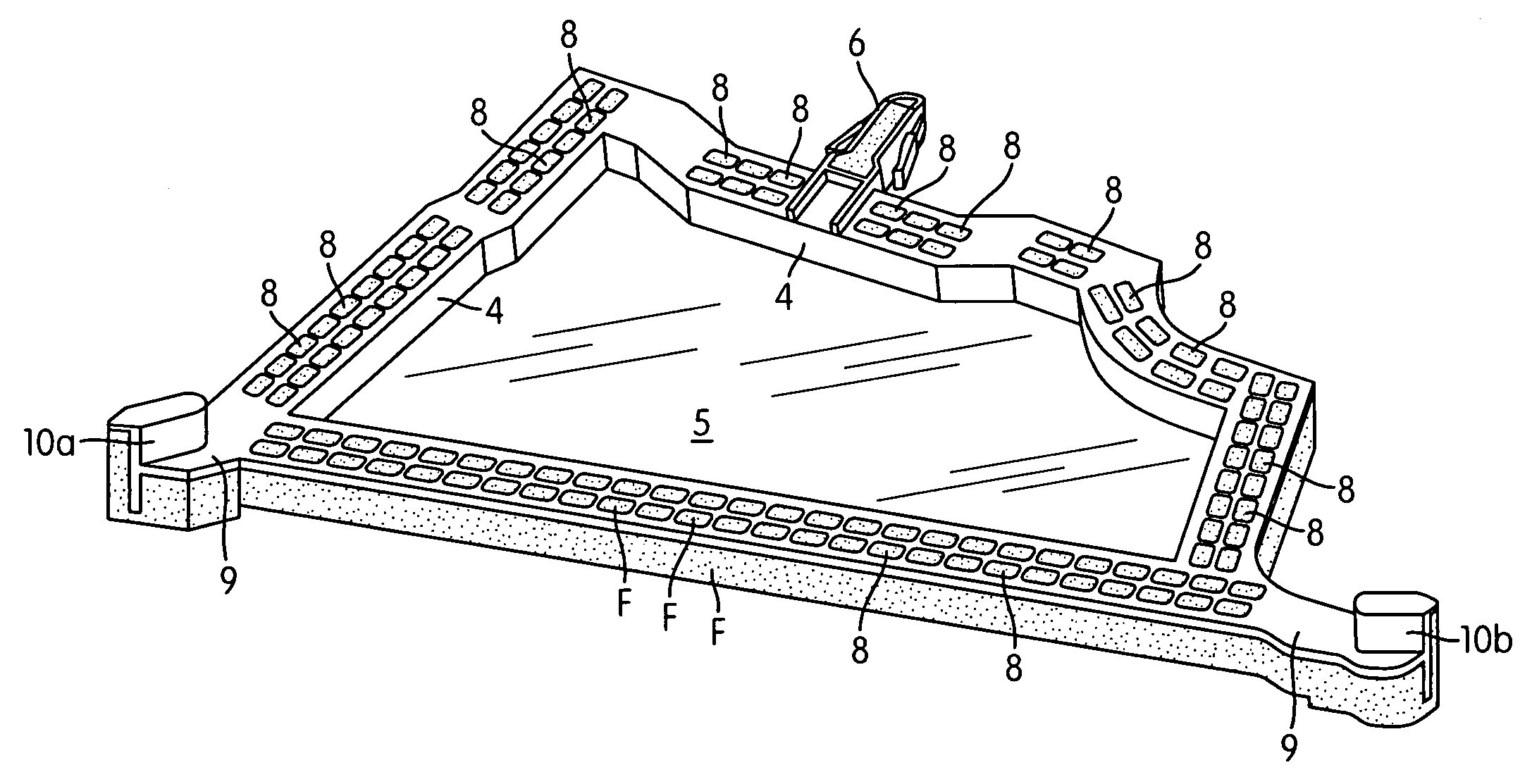
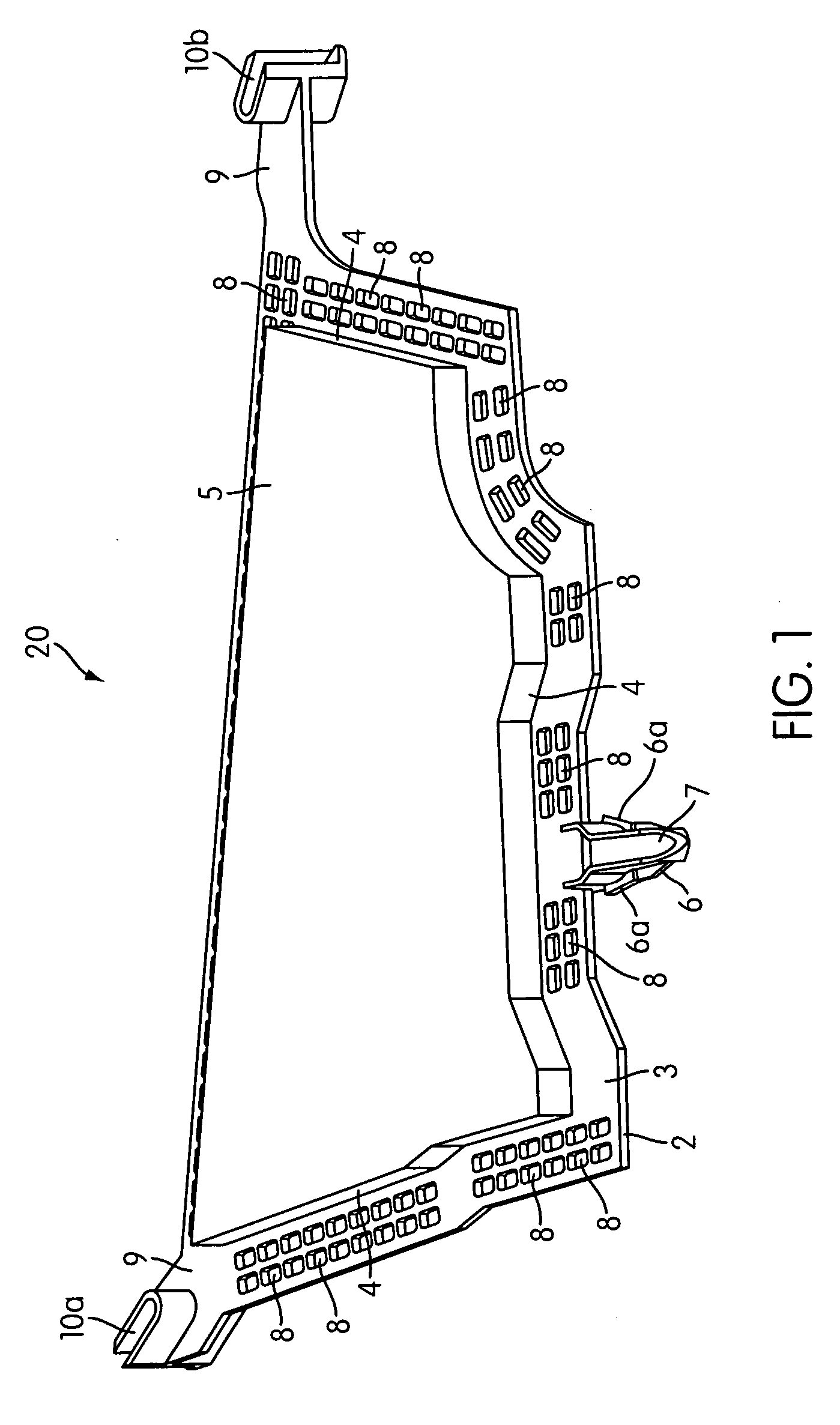
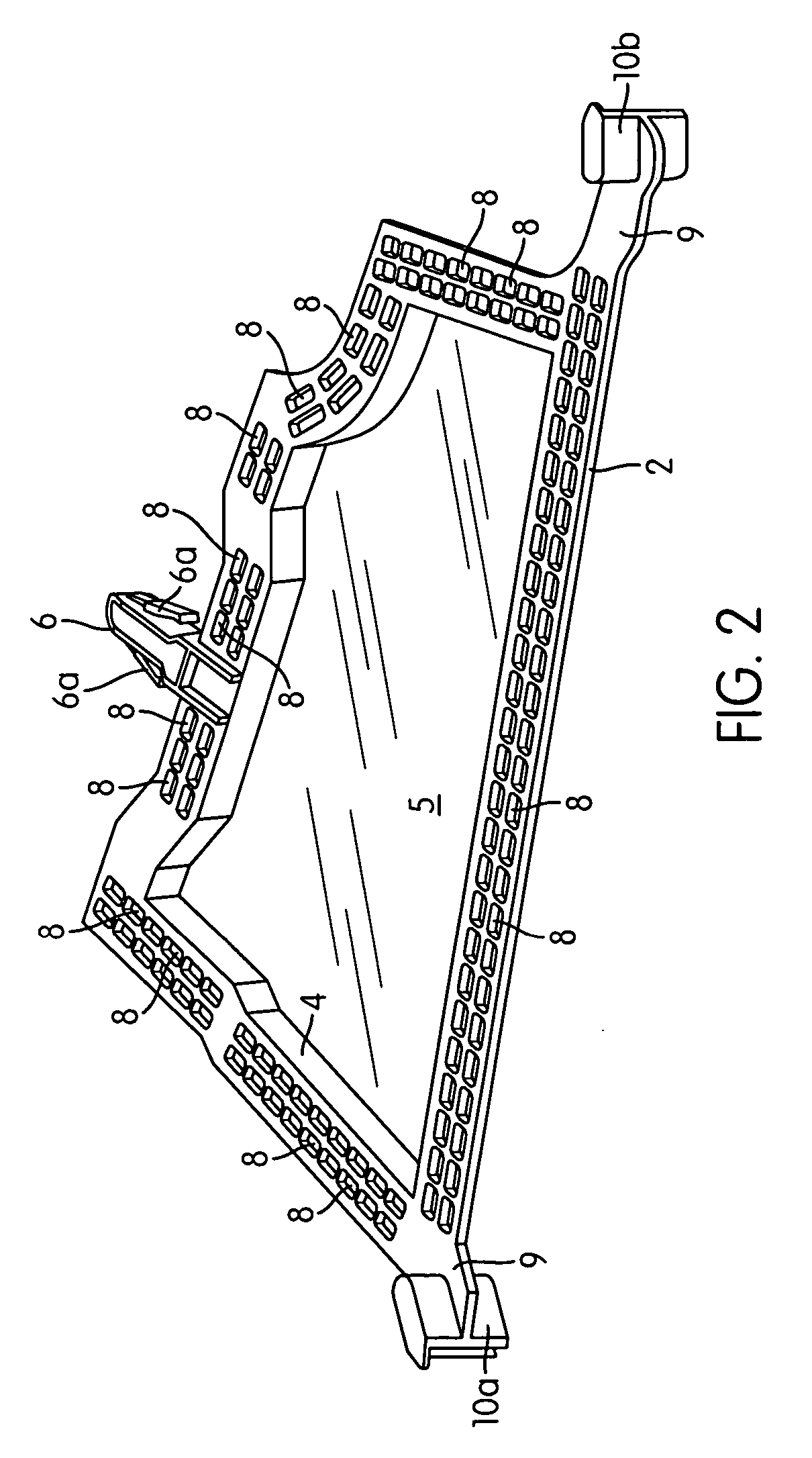
[0028] According to one embodiment of the present invention, the holding part (3) of the base body (2) is prepared with a large number of holes (8) that are preferably small and opened in a net or lattice pattern, and thereby a structure is prepared such that even the foamable material (F) in direct contact with the holding part (3) of the base body (2) can be directly heated without the heating from the outside being blocked by the base body (2), the heat-receiving efficiency is improved, and the foaming expansion efficiency of the foamable material is enhanced, so that good filler efficiency can be displayed within the cavity of the hollow structure.

[0029] When there are one or more corners in the transverse cross-sectional shape of the cavity of the hollow structure, it is desirable to provide one or more extensions (9) in the aforesaid base body (2) which correspond to the corners of the cavity of the hollow structure, and to provide approximately U-shaped foaming control walls...


PUM

PropertyMeasurementUnit
widthaaaaaaaaaa
diameteraaaaaaaaaa
heightaaaaaaaaaa

Abstract

The invention provides a holding jig for supporting and fixing a solid material capable of being foamed by application of heat in a cavity of a hollow structure. The holding jig may be provided with a plate-like base body made smaller in diameter than the cavity of the hollow structure, a holding part that is provided in a predetermined width in the form of a ring on the periphery of one side of said base body and supports one side of the foamable material, a step part with predetermined height, which is projected in the form of a ring at the inner peripheral end of said holding part and supports the inner peripheral surface of the foamable material, and an attaching means with which the base body can be freely attached to or detached from the hollow structure. The holding part can be provided with a plurality of small holes that open from one side to the other side of the base body, preferably in a net or lattice pattern. The holding jig may have one or more extensions containing approximately U-shaped foaming control walls that assist in directing expansion of the foaming material towards corners of the hollow structure.

Description

FIELD OF THE INVENTION [0001] The present invention pertains to a holding jig (also called a holder or carrier) for supporting and fixing a foamable material that is used to fill a cavity (also called a hollow space) of a hollow structure such as a pillar, rocker panel, or roof side panel of an automobile body and that is intended to fill up the cavity by foaming and expanding upon external heating, and to cavity fillers (also called hollow space blocking parts or baffles) and auxiliary cavity fillers for a hollow structure utilizing said holding jig. DISCUSSION OF THE RELATED ART [0002] Ordinarily, a foamable material is used to fill a cavity of a hollow structure such as a pillar of an automobile body, where this material foams and expands upon applying external heat of about 140-210° C. to the automobile body in the electrodeposition or baked finish process of the automobile, and has soundproofing and vibration damping effects such as improving the quietness within the car by blo...

Claims


Application Information

Patent Timeline
Patent Type & Authority Applications(United States)
IPC IPC(8): B29C44/02
CPCB29C44/18B60R13/08B62D29/002B29C70/745B29C70/747B29C44/12B29C70/68B29C44/1214B29C70/78
Inventor KANIE, HIDEKIKOUMURA, MASAHIKO
Owner CEMEDINE HENKEL
Why Eureka
Try Eureka