Integrated focusing and reflecting structure in an optical assembly

a technology of optical assembly and integrated structure, which is applied in the field of integrated structure for use in optical transmitters and receivers, can solve the problems of increasing the complexity and cost of the package, the number of parts and the number, and requiring environmental protection, so as to simplify the device design, simplify the construction, and reduce the complexity of the device

Active Publication Date: 2007-06-21
II VI DELAWARE INC
View PDF8 Cites 13 Cited by
  • Summary
  • Abstract
  • Description
  • Claims
  • Application Information

AI Technical Summary

Benefits of technology

[0015] The present invention has been developed in response to the above and other needs in the art. Briefly summarized, embodiments of the present invention are directed to an integrated reflecting and focusing structure for use in optical transmitters and receivers to redirect optical signals when an optoelectronic device of the transmitter or receiver is positioned in an off-center relationship with respect to an intended light path. The integrated reflecting and focusing structure simplifies construction while reducing complexity of the device. In one embodiment, an optical subassembly is disclosed and includes a housing and an optical fiber that is coupled to the housing. An optoelectronic component, such as a laser diode, is positioned in the housing and is configured to produce a light beam. The subassembly further includes an integrated focusing and reflecting prism that serves as a means for simultaneously redirecting and focusing the light beam while in transit between the laser diode and the optical fiber. The focusing feature combined with redirection of the light beam obviates the need for a separate lens assembly, thereby simplifying device design.

Problems solved by technology

Generally, these optoelectronic components are sensitive electrical devices, and therefore require environmental protection.
Repositioning components relatively closer to the laser and / or photodiode has presented various challenges, especially when such repositioning involves the inclusion of new components within the TO package itself.
The above off-center laser diode configuration, though often necessary, unfortunately adds to the complexity and cost of the TO package both in terms of the number of parts and the number of parameters that must be adjusted for to accurately align the laser diode, reflector, lens / lens assembly, and optical fiber.

Method used


Image

  • Integrated focusing and reflecting structure in an optical assembly
  • Integrated focusing and reflecting structure in an optical assembly
  • Integrated focusing and reflecting structure in an optical assembly

Examples


Embodiment Construction

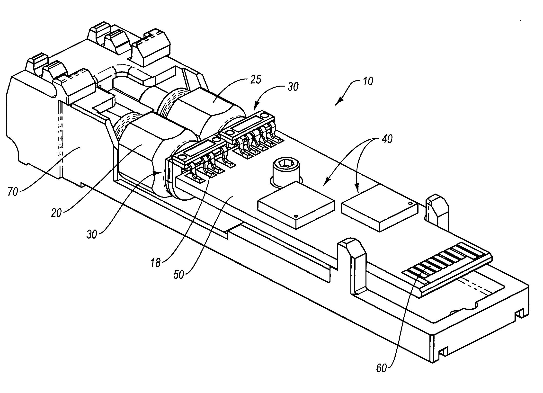
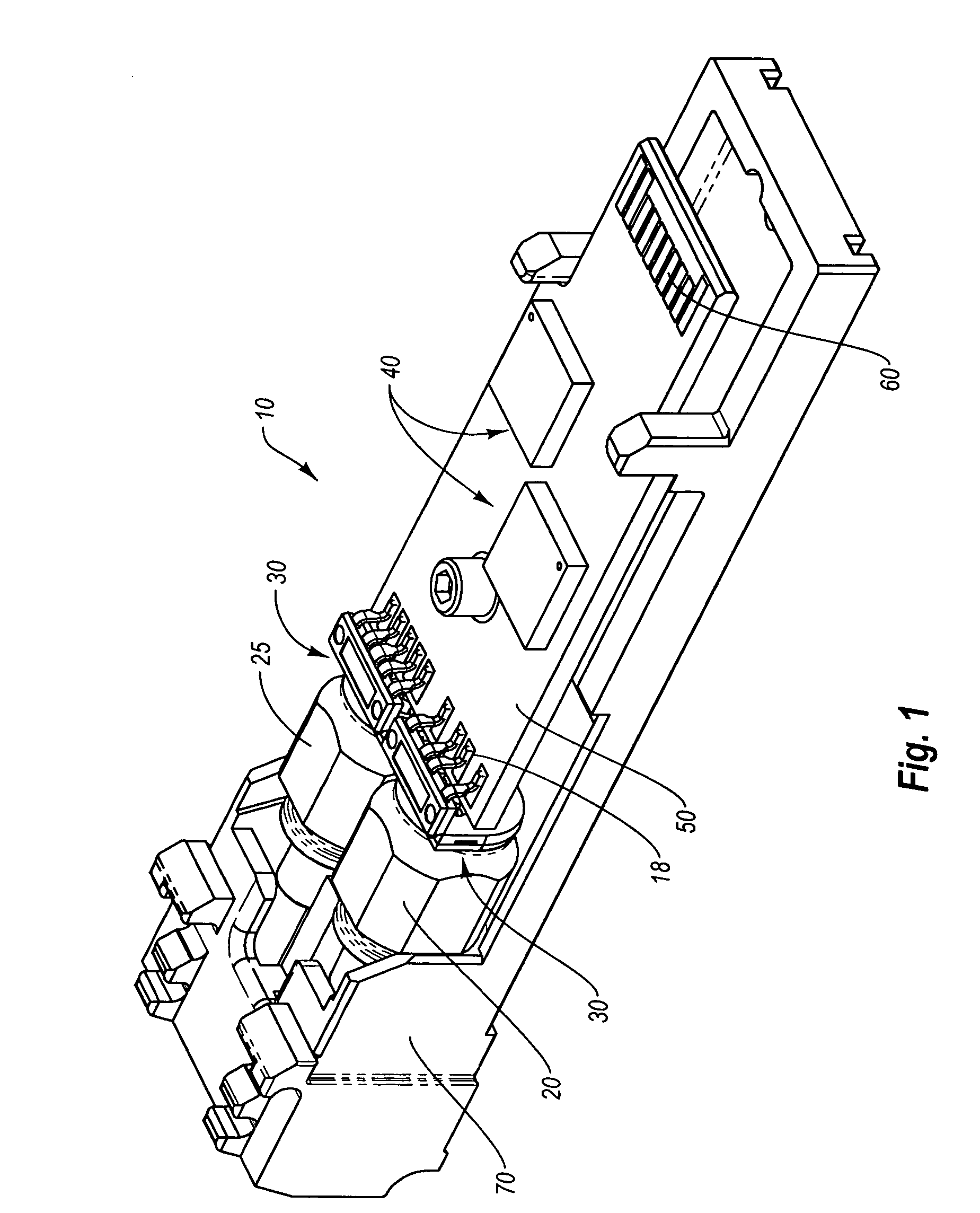
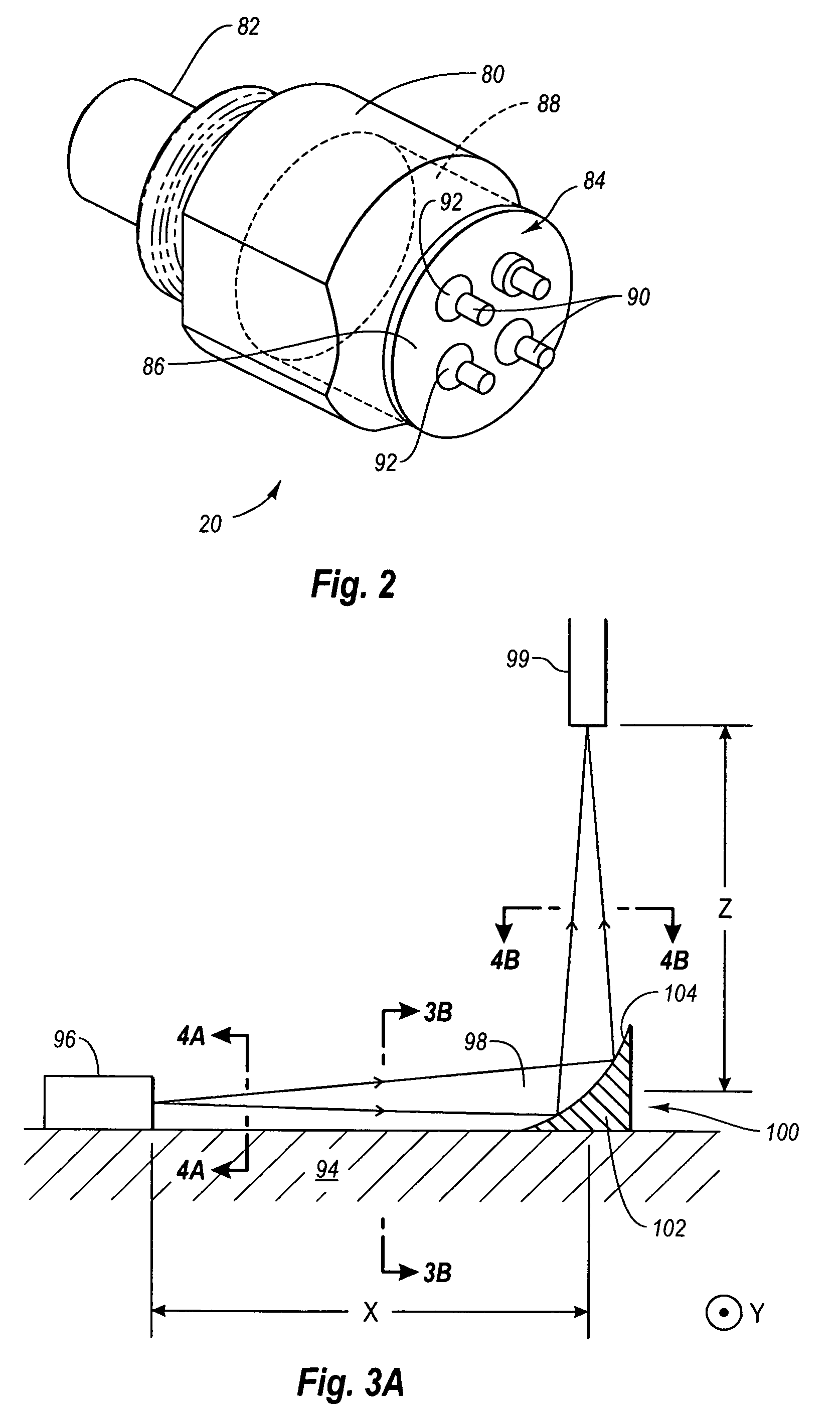
[0029] Reference will now be made to figures wherein like structures will be provided with like reference designations. It is understood that the drawings are diagrammatic and schematic representations of exemplary embodiments of the invention, and are not limiting of the present invention nor are they necessarily drawn to scale.

[0030]FIGS. 1-6 depict various features of embodiments of the present invention, which is generally directed to an integrated reflecting and focusing structure for use in optical transmitters and receivers to redirect optical signals when an optoelectronic device of the transmitter or receiver is positioned in an off-center relationship with respect to an intended light path. The integrated reflecting and focusing structure simplifies construction of the transmitter or receiver while reducing complexity of the device when alignment of device components is performed.

[0031] In the first exemplary embodiment to be described below, an optical transmitter is de...


PUM


Abstract

An integrated reflecting and focusing structure for use in optical transmitters and receivers to redirect optical signals when an optoelectronic device of the transmitter or receiver is positioned in an off-center relationship with respect to an intended light path is disclosed. The integrated reflecting and focusing structure simplifies construction while reducing complexity of the device. In one embodiment, an optical subassembly is disclosed and includes a housing and an optical fiber that is coupled to the housing. An optoelectronic component, such as a laser diode, is positioned in the housing and is configured to produce a light beam. The subassembly further includes an integrated focusing and reflecting prism that serves as a means for simultaneously redirecting and focusing the light beam while in transit between the laser diode and the optical fiber. The focusing feature combined with redirection of the light beam obviates the need for a separate lens assembly.

Description

BACKGROUND [0001] 1. Technology Field [0002] The present invention generally relates to optical transmitters and receivers. In particular, the present invention relates to an integrated structure for use in optical transmitters and receivers that enables focusing and redirecting of an optical signal to be simply performed. [0003] 2. The Related Technology [0004] Optical networking systems, including fiber-optics and optoelectronics, are an important aspect of modem networking circuits for their ability to allow for efficient, accurate, and rapid transmission of data between various components in the network system. As with most communications systems, the efficient use of space in optical networks is of ever-increasing importance. Further, design considerations for such networks must take into account the modularity of the particular components that are included in the network. [0005] Indeed, modular components are desirable in fiber optic systems to reduce the cost of manufacturing...

Claims


Application Information

Patent Timeline
Patent Type & Authority Applications(United States)
IPC IPC(8): G02B6/36
CPCG02B6/4206G02B6/4214G02B6/4246
Inventor CHEN, QINHSIEH, JOHN
Owner II VI DELAWARE INC
Why Eureka
Try Eureka