Method and system for passive optical network diagnostics

a technology of optical network and diagnostic method, applied in the field of passive optical network, can solve problems such as malfunction, and achieve the effect of reducing the operational expense (opex) of the carrier

Active Publication Date: 2007-06-21
MICROSEMI ISRAEL STORAGE SOLUTIONS LTD
View PDF11 Cites 55 Cited by
  • Summary
  • Abstract
  • Description
  • Claims
  • Application Information

AI Technical Summary

Benefits of technology

[0016] The present invention discloses a system and method for detecting and isolating problems and malfunctions in a PON without placing any physical test equipment anywhere. The system, centered on the OLT, is also referred to as an “OLT diagnostic system”. In some cases, a malfunction comes into play when errors are detected. In other cases, a measurement can alert a PON operator to a problem be

Problems solved by technology

In some cases, a malfunction comes

Method used


Image

  • Method and system for passive optical network diagnostics
  • Method and system for passive optical network diagnostics
  • Method and system for passive optical network diagnostics

Examples


Embodiment Construction

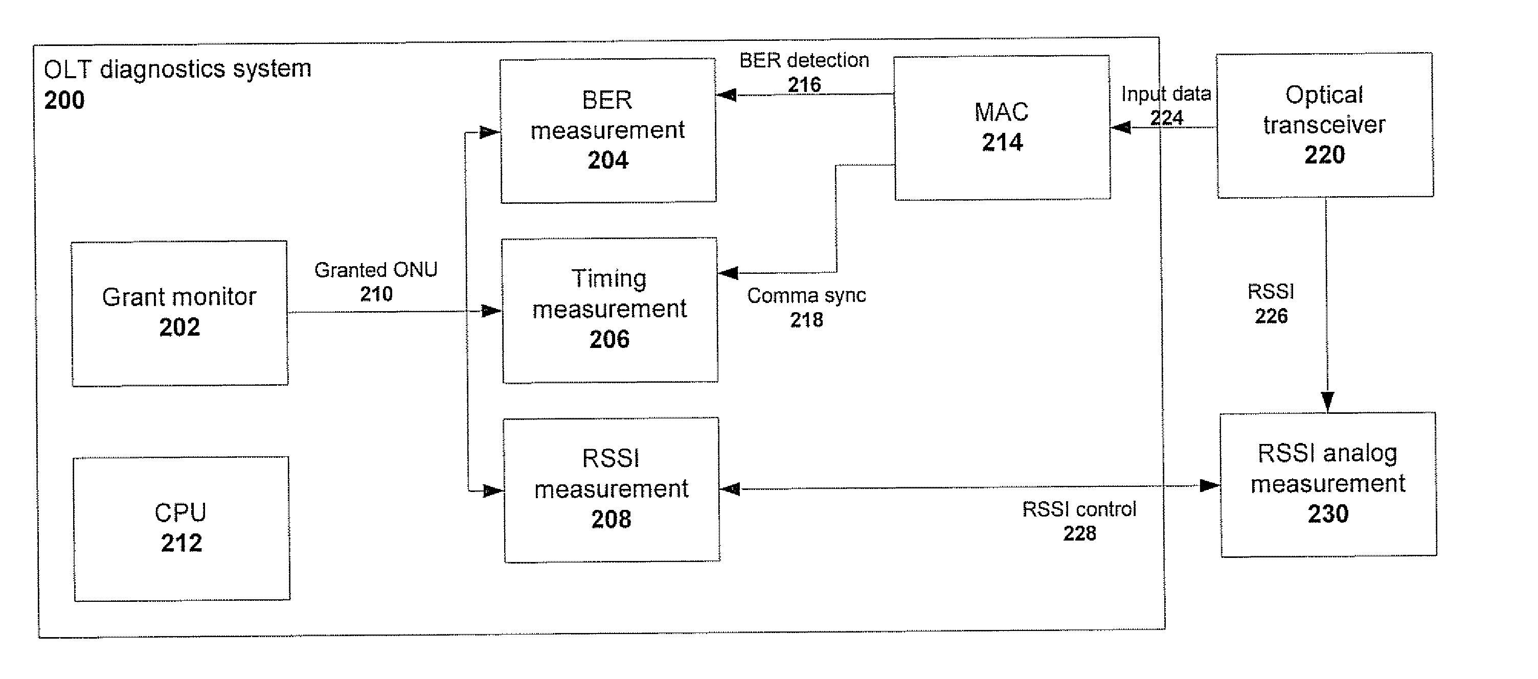
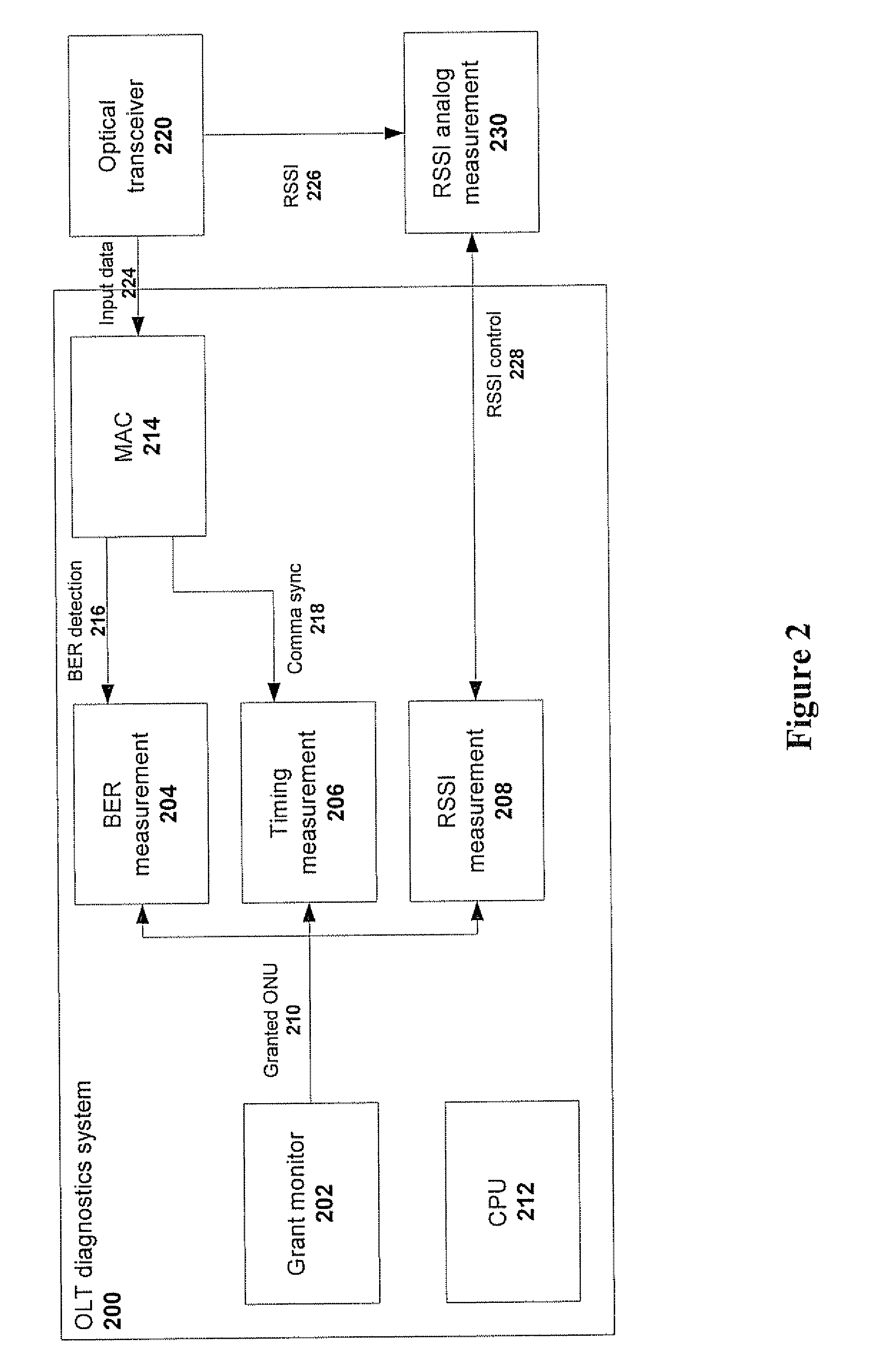
[0046] The present invention discloses a PON diagnostics system and method that provide an operator with the ability to identify and isolate problems in teal time in a PON. The system includes software (SW) that can analyze the collected results and provide information about existing or potential malfunctions / problems. The diagnostics method provides to an operator one or more of the following parameters:

[0047]“Laser power”, presented per ONU and measured with the subsystem of FIG. 3.“

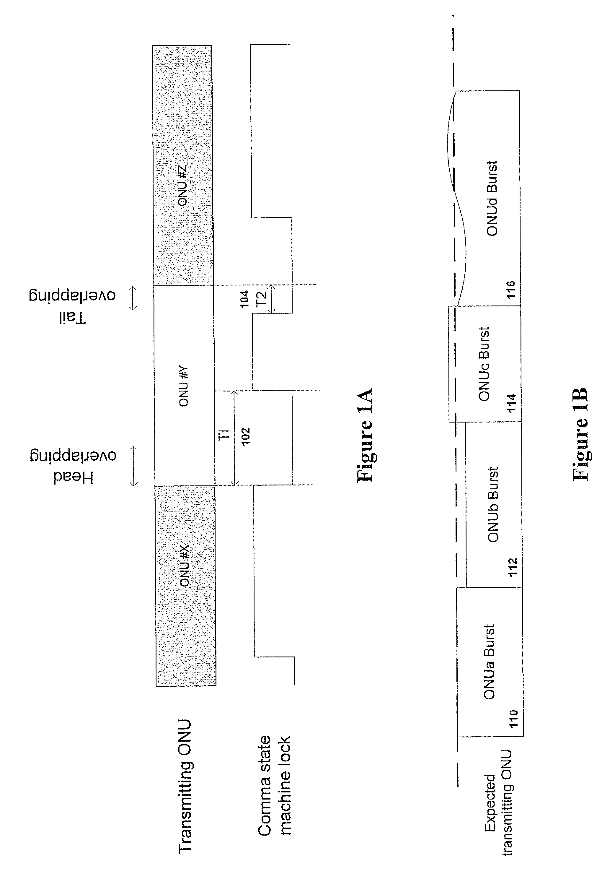
[0048]“Sync-lock and -unlock time”, i.e. the actual time the ONU starts and ends its transmission relative to an expected time, measured with the subsystem of FIG. 4.

[0049]“Bit error”, included in the IEEE802.3ah standard and presented per ONU on a time scale from grant start or grant end.

[0050] The type of malfunction is identified, per ONU or group of ONUs, from an analysis of one parameter or a combination of these parameters.

[0051] The bit error rate for each ONU is sampled periodically. If the...


PUM


Abstract

A method and system for identifying faults in a passive optical network (PON), The method comprises acquiring at an optical network terminal of the PON at least one parameter indicative of at least one malfunction in at least one optical network unit of the PON, and identifying each malfunction from the at least one parameter The parameters measured include, for each ONU, laser power, sync-lock and -unlock time and bit error rates. The information at the OLT is acquired remotely and in digital form, without use of any physical probing of any point or element in the PON. The system includes a temporal measurement module and a power laser measurement module coupled to a central processing unit that can extract fault information from digital data processed in the two modules.

Description

[0001] This patent application claims the benefit of PCT Patent Application No. PCT / IL05 / 001358, filed Dec. 19, 2005, which claims the benefit of U.S. Patent Application No. 60 / 699,879 filed Jul. 18, 2005.FIELD OF THE INVENTION [0002] The present invention relates generally to passive optical networks (PON) and more particularly to active real time monitoring of such networks BACKGROUND OF THE INVENTION [0003] Passive optical networks, and in particular Ethernet PONs (EPONs) are known, and described for example in U.S. Patent Application No, 20020196801 by Haran et al. The debugging of a running / active network in a shared media network environment is difficult. At the same time, the ability to proactively monitor the network and to verify that its behavior is correct is valuable. Isolating transmission errors (or simply “errors”), detecting the cause of an error and providing debugging tools are highly desired features in a network environment. [0004] A major goal in a PON that comp...

Claims


Application Information

Patent Timeline
IPC IPC(8): H04B10/08H04B10/00H04B10/079
CPCH04B10/0793H04B10/07953H04Q11/0067H04Q2011/0081H04Q2011/0083H04B10/077H04B10/07955H04Q11/0066H04B10/0799H04Q2213/1301
Inventor HARAN, ONN
Owner MICROSEMI ISRAEL STORAGE SOLUTIONS LTD
Why Eureka
Try Eureka