Gas turbine engine provided with a foreign matter removal passage

a technology of gas turbine engine and foreign matter, which is applied in the direction of combustion-air/fuel-air treatment, separation process, filtration separation, etc., can solve the problems of large amount of time and cost required to remove foreign matter, increase the complexity of the system and cost, and the control system could fail, so as to achieve efficient compression and improve combustion efficiency , the effect of simplifying the passage arrangement for conducting foreign matter

Active Publication Date: 2007-06-28
HONDA MOTOR CO LTD
View PDF3 Cites 24 Cited by
  • Summary
  • Abstract
  • Description
  • Claims
  • Application Information

AI Technical Summary

Benefits of technology

[0011] Thus, as the combustion air mixed with foreign matters flows in the intake passage, owing to the inertia which is greater for the foreign matters having a greater density than air, the foreign matters tend to travel more straight than the air so that most of the foreign matters that have been introduced into the intake passage are selectively passed into the foreign matter removal passage, and then to the bypass passage. Also, because the configuration of the intake passage forces the combustion air toward the rotary shaft, the combustion air can be efficiently compressed and the combustion efficiency can be thereby improved.
[0012] According to a preferred embodiment of the present invention, the foreign matter removal passage is defined between the inner casing and outer liner at least in a region adjacent to the curved portion or reduced diameter portion of the intake passage. Thereby, the passage arrangement for conducting the foreign matters can be simplified, and the position and number of the openings formed in the intake passage and bypass duct for communication with the foreign matter removal passage can be selected freely.
[0013] Typically, the first compressor comprises a centrifugal compressor, and an upstream end of the intake passage is provided with a second compressor comprising an axial flow compressor. If the foreign matter introduction openings are formed in a part of the outer liner corresponding to a part of the intake passage extending into a front end of the first compressor, the pressure produced by the first compressor helps the foreign matters to be forced into the foreign matter removal passage. Also, if the first compressor consists of a centrifugal compressor which has a front end having a relatively small diameter and a rear end having a relatively large diameter, by making a part of the bypass duct corresponding to the curved portion of the intake passage curve radially outward, a relatively large annular space can be defined between the intake passage and bypass passage adjacent to the front end of the first compressor, and it can be conveniently used as the foreign matter removal passage.
[0014] If the foreign matter introduction openings are formed in the outer liner in a circumferential arrangement, foreign matters can be evenly removed from the combustion air. If the foreign matter introduction openings are each provided with an elongated configuration selected from a group consisting of a slot, an elliptic hole and a rectangular hole, and each foreign matter introduction opening provided with an elongated configuration has a lengthwise axis slanted with respect to the central axial line, relatively large foreign matters can be removed without unduly reducing the rigidity of the outer liner.
[0015] If the foreign matter ejection holes are formed in the inner casing in a circumferential arrangement, foreign matters can be evenly removed from the combustion air that has flowed into the foreign matter removal passage.
[0016] According to a preferred embodiment of the present invention, the foreign matter ejection holes are formed in a part of the inner casing recessed from a general wall surface of the inner casing facing the bypass duct. Because the propulsion airflow in the bypass duct produces a region of reduced pressure in such a recessed part, the air mixed with foreign matter can be effectively drawn from the foreign matter removal passage to the bypass duct. This effect is particularly enhanced if the recess part is covered by a lid plate which defines an opening in a rear edge thereof.

Problems solved by technology

When the arrangement for removing foreign matters disclosed in the mentioned Japanese patent laid open publication is applied to an aircraft turbofan engine, the following problems associated with the removal of foreign matters arise.
Therefore, large amounts of time and cost were required when removing foreign matters.
The use of a solenoid valve that can automatically open and close eliminates the need to dismantle the casing, but the necessary control system for controlling the opening and closing of the solenoid valve adds to the complexity of the system and the cost.
Also, such a control system could fail.

Method used


Image

  • Gas turbine engine provided with a foreign matter removal passage
  • Gas turbine engine provided with a foreign matter removal passage
  • Gas turbine engine provided with a foreign matter removal passage

Examples


Embodiment Construction

[0025] Now the present invention is described in the following in more detail in terms of a concrete embodiment with reference to the appended drawings.

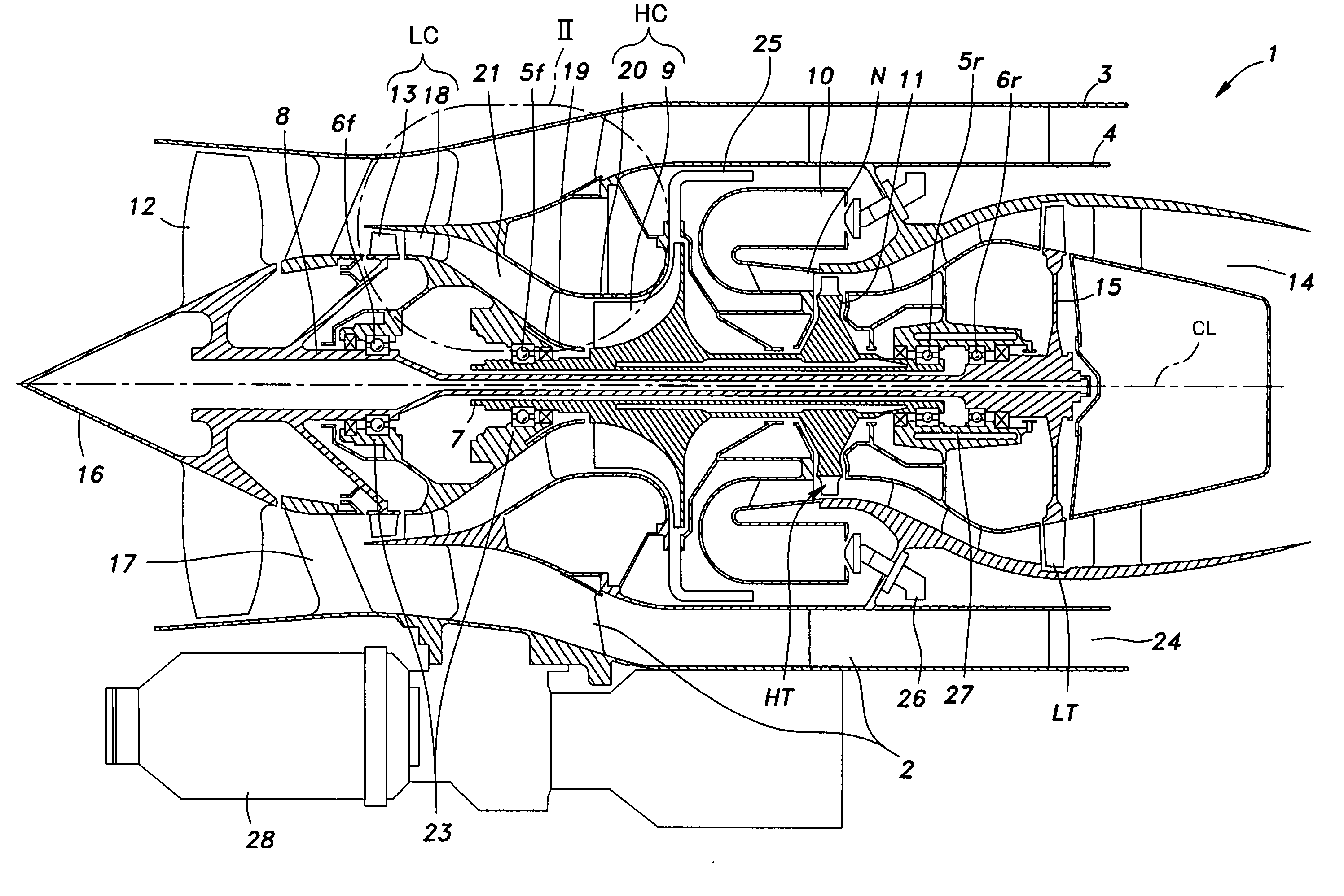
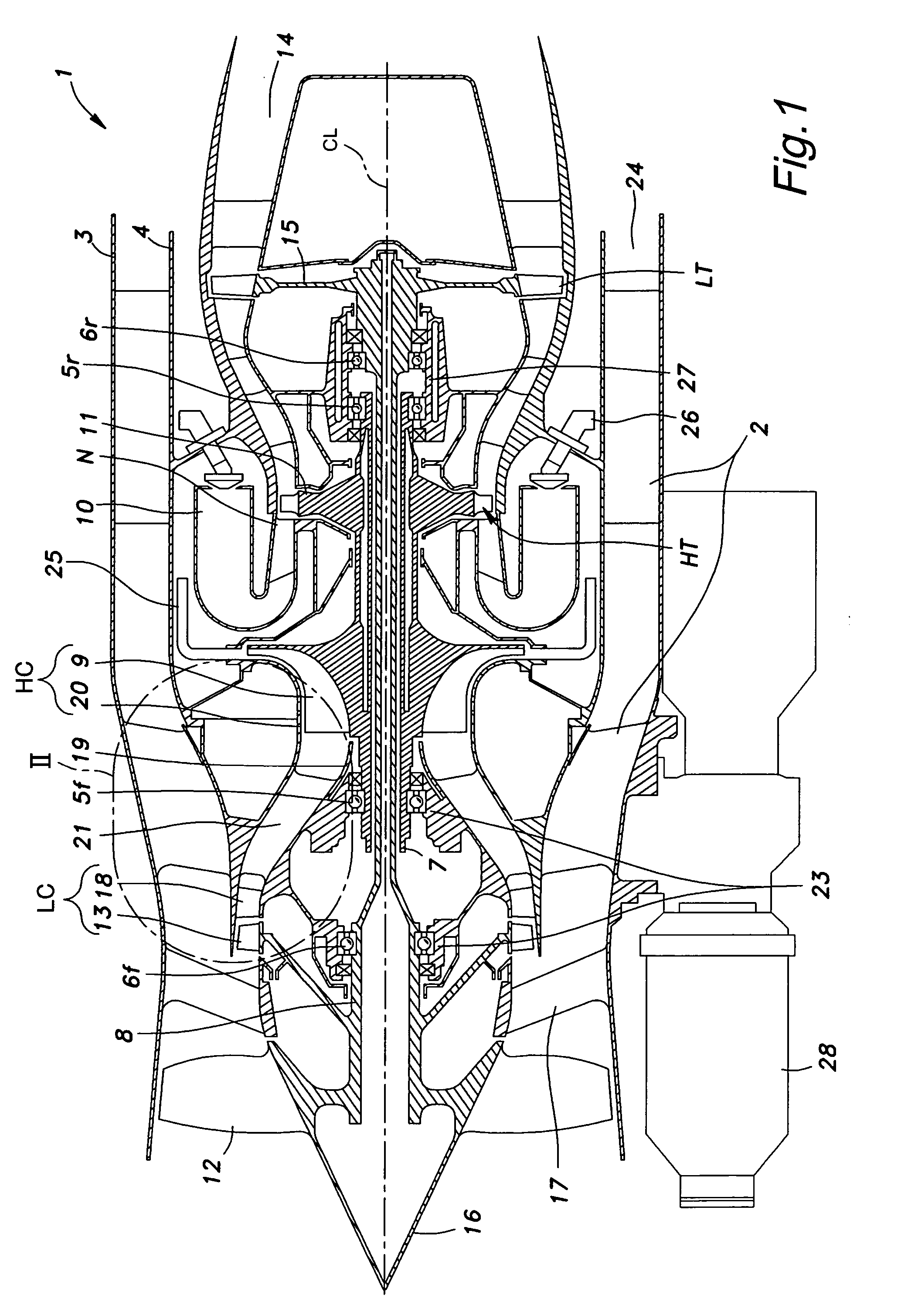
[0026]FIG. 1 is a simplified overall view of a turbofan engine (which is referred to simply as “engine” hereinafter). This engine 1 comprises an outer casing 3 and an inner casing 4 which are both cylindrical in shape and disposed in a mutually coaxial relationship joined by straightening vanes 2. The engine 1 further comprises a rotary shaft including an outer shaft 7 and an inner shaft 8 which are centrally supported in the inner casing 4 by mutually independent bearings 5f, 5r, 6f and 6r. “CL” in the drawing denotes the central axial line (rotative axial line) of the outer shaft 7 and inner shaft 8.

[0027] The outer shaft 7 is integrally provided with an impeller wheel 9 for a high pressure centrifugal compressor (second compressor means) HC at a front end thereof and a high pressure turbine wheel 11 for a high pressure turbine H...


PUM

PropertyMeasurementUnit
angleaaaaaaaaaa
diameteraaaaaaaaaa
temperatureaaaaaaaaaa

Abstract

[Object] To provide a gas turbine engine which is simple in structure but can effectively remove foreign matters from the combustion air.
[Means] The intake passage 21 includes an inlet portion 29, a curved portion 30 and a reduced diameter portion 31. The bypass duct 24 is curved away from the central axial line CL in a region corresponding to the curved portion 30 and reduced diameter portion 31 of the intake passage 29. Between the intake passage 29 and bypass duct 24 is defined an annular space 32. In the reduced diameter portion 31, the outer liner 20 is formed with a large number of foreign matter introduction openings 33 in a circumferential arrangement for communication between the intake passage 21 and annular space 32. The inner casing 4 is formed with a plurality of foreign matter ejection holes 34 in a circumferential arrangement in a part thereof that curves outward for communication between the annular space 32 and bypass duct 24.

Description

TECHNICAL FIELD [0001] The present invention relates to a gas turbine engine primarily for use in aircraft, and in particular to a technology for preventing the intrusion of dust and water into the combustion chamber. BACKGROUND OF THE INVENTION [0002] There are various types of gas turbine engine for use in aircraft, but turbofan engines are by far most commonly used in passenger planes and cargo planes. In a turbofan engine, the combustion gas of the gas turbine is expelled rearward and a propeller fan (front fan) provided immediately downstream of the air inlet is driven by the drive shaft of the gas turbine engine. In such a gas turbine engine, a large part of the air drawn into the engine by the front fan is expelled from the rear end of the engine as a propelling airflow while a remaining part of the air is introduced into the combustion chamber of the gas turbine engine as combustion air. In the turbofan engine, combustion gas of high temperature and high pressure is produced...

Claims


Application Information

Patent Timeline
Patent Type & Authority Applications(United States)
IPC IPC(8): F02C7/052
CPCF02C7/05F02C7/052F02K3/06F05D2220/326F05D2220/327F05D2260/607F05D2250/323F05D2250/71Y02T50/675Y02T50/60
Inventor KAWAMOTO, OSAMUNAGATA, HIROKIFUKUTANI, MASAYUKIOANA, MINEYASU
Owner HONDA MOTOR CO LTD
Why Eureka
Try Eureka