Exhaust gas purification apparatus, exhaust gas purification method, and sulfur component trapping agent for internal combustion engine

a technology of exhaust gas purification and purification method, which is applied in the direction of mechanical equipment, machines/engines, surface coverings, etc., can solve the problems of deteriorating catalyst activity and difficulty in purifying nox

Inactive Publication Date: 2007-06-28
BABCOCK HITACHI KK
View PDF8 Cites 11 Cited by
  • Summary
  • Abstract
  • Description
  • Claims
  • Application Information

AI Technical Summary

Problems solved by technology

Three way catalysts that have been used for exhaust gas purification of engines for theoretical air fuel ratio (stoichiometry) combustion have difficulty in purifying NOx.
However, it has been known that since the exhaust gas from the lean burn engines contains SOx derived from sulfur contained in gasoline, activity of the catalysts is deteriorated by SOx, which reacts with components in the NOx trapping catalysts.

Method used


Image

  • Exhaust gas purification apparatus, exhaust gas purification method, and sulfur component trapping agent for internal combustion engine
  • Exhaust gas purification apparatus, exhaust gas purification method, and sulfur component trapping agent for internal combustion engine
  • Exhaust gas purification apparatus, exhaust gas purification method, and sulfur component trapping agent for internal combustion engine

Examples


embodiment 1

Installation of Sulfur Component Oxidizing Catalyst

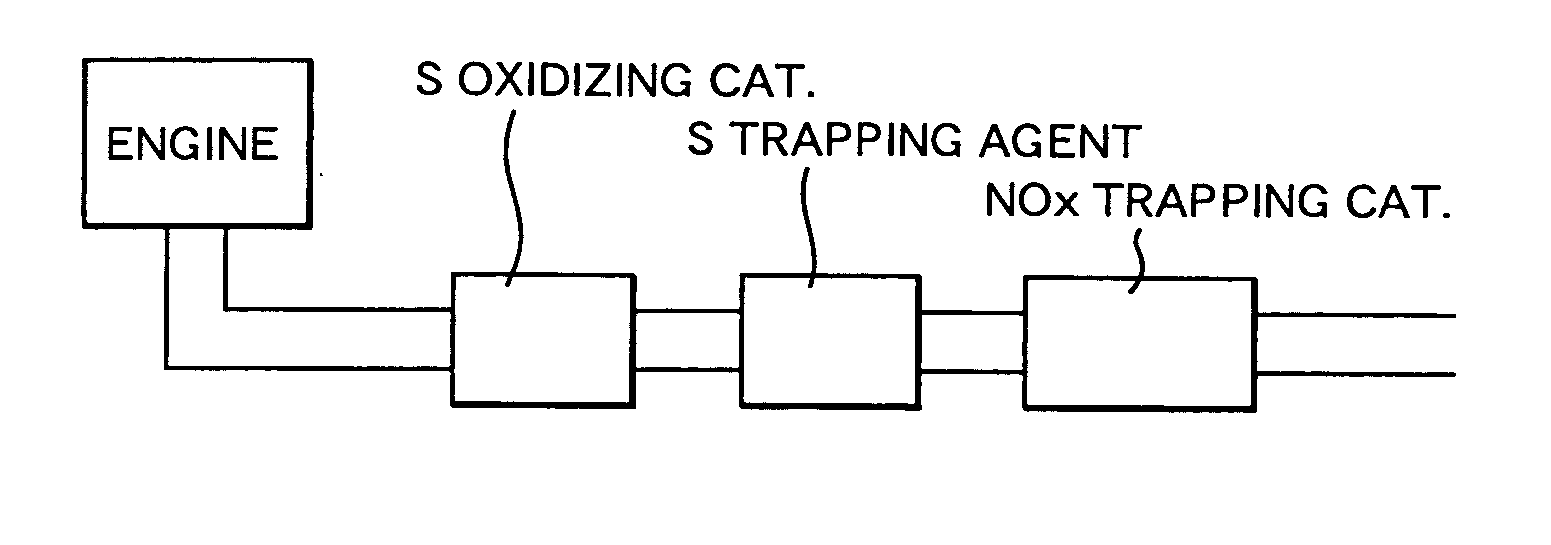
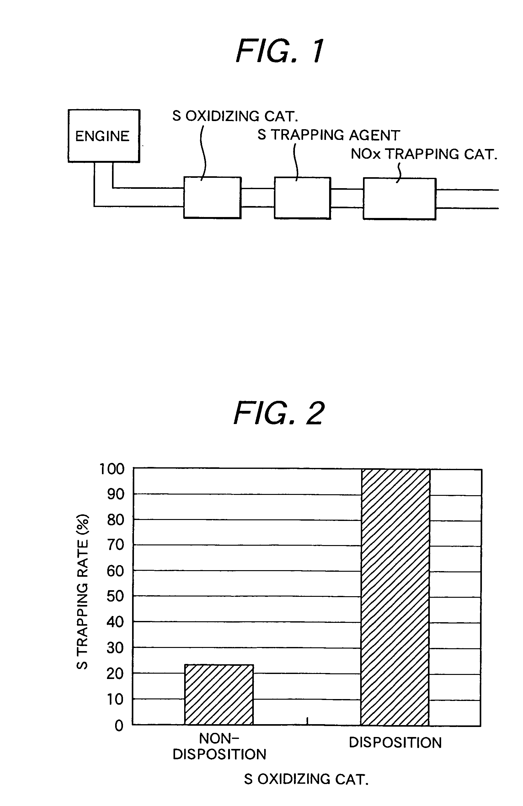
[0070] As shown in FIG. 1, the sulfur component trapping agent B (Na2CO3) was installed before the NOx trapping catalyst 1 in an engine exhaust gas duct. Further, a sulfur component oxidizing catalyst was disposed before the sulfur component trapping agent to constitute a purification apparatus. As the sulfur component oxidizing catalyst, Al2O3 with Pt prepared in the same manner as in the method for preparing the NOx trapping catalyst was used. The sulfur component oxidizing catalyst comprises 190 g of alumina per 1 liter of the honeycomb, 2.792 g of Pt, in conversion of elements.

[0071] In FIG. 1, a comparative embodiment 1 had no sulfur component oxidizing catalyst. SOx containing lean gas was supplied to the sulfur component trapping agents to evaluate sulfur trapping rates by the sulfur component trapping agents.

[0072] Temperatures of the sulfur component oxidizing catalysts and sulfur component trapping agents were 400 degre...

embodiment 2

Evaluation of Sulfur Component Trapping Performance of the Sulfur Component Trapping Agent

[0077] In the system shown in FIG. 1, amounts of sulfur trapped by the sulfur component trapping agent were calculated in a thermodynamic method when SOx containing lean gas was supplied to the sulfur component trapping agent. As calculation software, MALT2 (thermodynamic database for personal computer; Japan Society of thermodynamics) was used.

[0078] A temperature of the sulfur component trapping agent was 300° C. A flow rate of the SOx containing lean gas was 3 L / min. The sulfur components in the gas were oxidized to SO3 by the sulfur component oxidizing catalyst disposed before the sulfur component trapping agent. Thus, a concentration of SO3 was estimated as 150 ppm. A period of flow time was 1000 hours. Gas components other than SO3 were shown in Table 3. The sulfur trapping rates were calculated by the equation (6).

TABLE 3Sulfur trapping rates of the sulfur component trappingagents A,...

embodiment 3

Evaluation on Decomposition Sulfates of Sulfur Component Trapping Agents

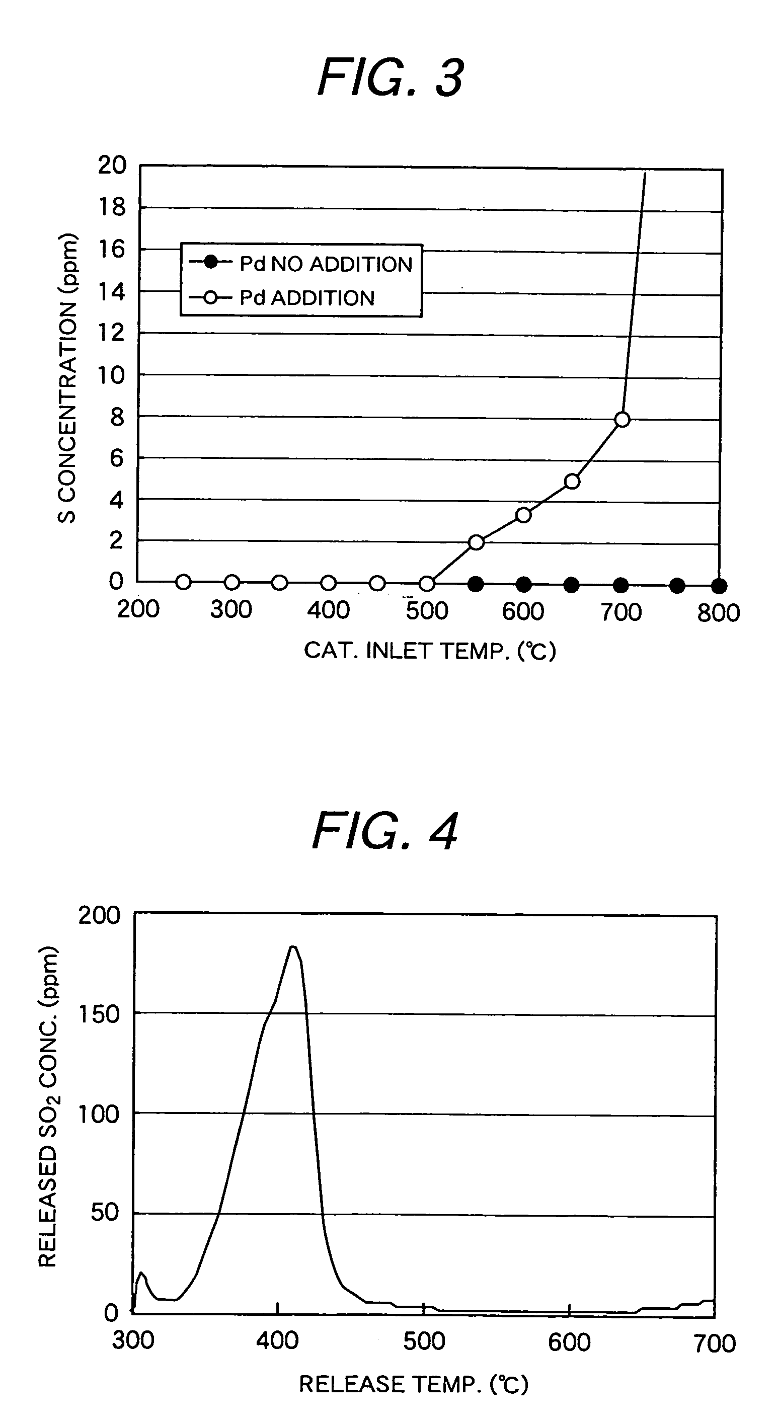
[0083] Decomposition of sulfates of the sulfur component trapping agents was evaluated. Sulfates / Al2O3 prepared by drying and mixing various sulfates and Al2O3 were used. A concentration of the sulfur component trapping agents per 10 grams of alumina was 0.04 mol in conversion of elements.

[0084] As samples of sulfates of the sulfur component trapping agents, sulfates of alkali metals, alkaline earth metals, and sulfates of Ce, Al, La, Y and Ni were chosen.

[0085] Powders of the above sulfur component trapping agents were granulated into 0.85 to 1.70 mm diameter. The temperature of the sulfur trapping agents was kept at 300° C. and the rich gas shown in Table 4 was flown through the trapping agents, while elevating a temperature of from 250 to 750° C. Concentrations of sulfur components (SO2+H2S) released from the trapping agents were measured. A space velocity SV of the gas was 30,000 / h.

TABLE 4Gas compositio...


PUM


Abstract

An object of the present invention is to provide a new exhaust gas purification apparatus for an internal combustion engine operated under a condition of an air fuel ratio leaner than a theoretical air fuel ratio, a method for purification of exhaust gas and an exhaust gas purification catalyst, which is suitable for suppressing degradation of the NOx purification catalyst by sulfur components.
An exhaust gas purification apparatus for an internal combustion engine, which comprises an exhaust gas passage for an internal combustion engine into which exhaust gas of lean air fuel ratio and rich or stoichiometric air fuel ratio flows, a NOx trapping catalyst that functions to trap NOx in the exhaust gas when the air fuel ratio is lean, a sulfur component trapping agent for trapping sulfur components in the exhaust gas, which is disposed before the NOx trapping catalyst, and a catalyst for oxidizing the sulfur components, which is disposed before the sulfur component trapping agent, wherein the sulfur component trapping agent has a trapping rate of 85 % or more of an amount of inflow sulfur in a trapping test at a flow rate of 150 ppm SO3-5% O2—balance being N2 gas per 1.5 moles of the sulfur trapping agent at 300° C. and a space velocity of 30,000/h for 1 hour; and the sulfur component trapping agent has a release rate of sulfur amount of 5 % or less of sulfur trapped in the sulfur component trapping agent in a release test under a flow of a 3000 ppm H2-600 ppm C3H6-3000 ppm O2-3.5 % CO—balance being N2 gas at a temperature elevation rate of 10° C. /min from 250 to 750° C. at an sulfur component trapping agent entrance, after the trapping test.

Description

TECHNICAL FIELD [0001] The present invention relates to an exhaust gas purification apparatus and exhaust gas purification method for an internal combustion engine operated under a lean burn condition, wherein fuel is leaner than a theoretical air / fuel ratio. BACKGROUND ART [0002] In recent years, there have been attention to lean burn engines for lean fuel combustion in terms of an air fuel ratio. The air fuel ratio represents a ratio of air to fuel in gas. [0003] Three way catalysts that have been used for exhaust gas purification of engines for theoretical air fuel ratio (stoichiometry) combustion have difficulty in purifying NOx. Thus, exhaust gas purifying catalysts for lean burn engines are investigated. One of them is disclosed in Japanese patent laid-open 11-319564(Patent publication 1) is disclosed. The publication discloses one of NOx absorbing metal oxides selected from alkali metals, alkaline earth metals and rare earth metals and a noble metal supported on a porous supp...

Claims


Application Information

Patent Timeline
Patent Type & Authority Applications(United States)
IPC IPC(8): F01N3/00F01N3/10F01N7/00F01N3/02F01N3/023F01N3/035F01N3/08F01N3/20F01N3/28
CPCF01N3/035F01N3/0807F01N3/0814F01N3/0842F01N3/085F01N3/106F01N2510/0682F01N2570/14Y02T10/24F01N13/0097F01N13/009Y02A50/20Y02T10/12
Inventor KANEEDA, MASATOIIZUKA, HIDEHIROHIGASHIYAMA, KAZUTOSHIKITAHARA, YUICHIKURODA, OSAMU
Owner BABCOCK HITACHI KK
Why Eureka
Try Eureka