Valve timing control device

Inactive Publication Date: 2007-06-28
TOYOTA JIDOSHA KK
View PDF2 Cites 16 Cited by
  • Summary
  • Abstract
  • Description
  • Claims
  • Application Information

AI Technical Summary

Benefits of technology

[0040] The third aspect of the present invention can change the status of the intake adjustment mechanism to provide the intake valve with valve opening timing that is retarded from the exhaust top dead center. In a region subsequent to the exhaust stop dead center, the in-cylinder pressure prevailing when the intake valve is open becomes negative to increase the intake flow velocity when the intake valve opening timing is retarded. Therefore, the third aspect of the present invention can properly increase the intake flow velocity.
[0041] The fourth aspect of the present invention can vary the intake valve lift amount by changing the status of the intake adjustment mechanism. The smaller the intake valve lift amount, the higher the intake flow velocity. Therefore, the fourth aspect of the present invention can properly increase the intake flow velocity.
[0042] The fifth aspect of the present invention can increase the intake flow velocity when internal combustion engine warm-up progresses. Therefore, the fifth aspect of the present invention can facilitate the atomization of the fuel in accordance with the progress in a warm-up process. Meanwhile, the fuel adhering to the neighborhood of the exhaust valve does not affect the emission when the warm-up process progresses. Therefore, the fifth aspect of the present invention can provide a good operating state without deteriorating the emission during the internal combustion engine warm-up process.
[0043] When the warm-up process progresses, the sixth aspect of the present invention can advance the retarded valve closing timing, that is, the exhaust valve closing timing, thereby increasing the intake flow velocity. Therefore, the sixth aspect of the present invention can facilitate the atomization of the fuel in accordance with the progress in the warm-up process. Meanwhi

Problems solved by technology

However, while the internal combustion engine is sufficiently low, the fuel adhering to the neighborhood of the exhaust valve cannot become vaporized in a cylinder and may be discharged as a

Method used


Image

  • Valve timing control device
  • Valve timing control device
  • Valve timing control device

Examples


first embodiment

[Configuration of a First Embodiment]

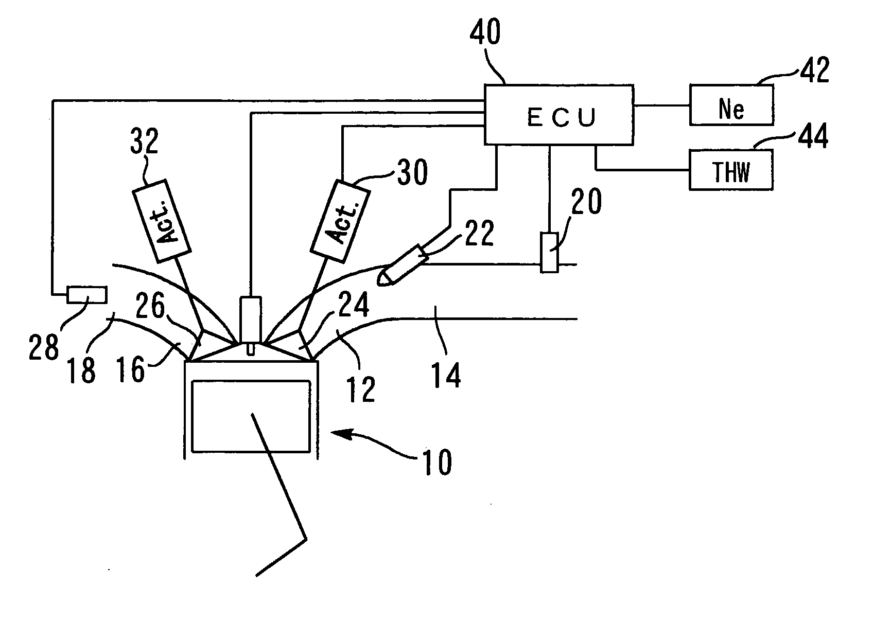
[0056]FIG. 1 illustrates the configuration of a first embodiment of the present invention. A system according to the first embodiment includes an internal combustion engine 10. The internal combustion engine 10 includes a plurality of cylinders. One of the plurality of the cylinders is shown in FIG. 1. Each cylinder communicates with an intake path 14 via an intake port 12 and communicates with an exhaust path 18 via an exhaust port 16.

[0057] The intake path 14 is provided with an air flow meter 20 for detecting an intake air amount Ga. The intake port 12 is provided with a fuel injection valve 22 for injecting fuel into the intake port 12. Each cylinder has two intake valves 24 (only one of them is shown in FIG. 1). When the intake valves 24 open or close, the interior of the cylinder is connected to or disconnected from the intake port 12.

[0058] Each cylinder also has two exhaust valves 26. When the exhaust valves 26 open or close, the inter...

second embodiment

[0106] A second embodiment of the present invention will now be described with reference to FIGS. 8A, 8B, 9, and 10. The system according to the second embodiment of the present invention can be implemented by adopting the hardware configuration of the first embodiment and allowing the ECU 40 to execute routines shown in FIGS. 9 and 10 instead of the routine shown in FIG. 7.

[Features of the Second Embodiment]

[0107] Under predefined operating conditions, the system according to the present embodiment is requested to perform a one-valve-stopped operation during which one of the two exhaust valves 26 provided for each cylinder of the internal combustion engine 10 is stopped. The one-valve-stopped operation is demanded immediately after a cold start of the internal combustion engine 10 or in other similar situations where the internal combustion engine 10 is to be warmed up promptly.

[0108] If one of the two exhaust valves 26 is kept closed during an exhaust stroke, the gas burned in ...


PUM


Abstract

An intake port of an internal combustion engine 10 is provided with a fuel injection valve 22. An intake adjustment mechanism 30 for varying the valve timing of an intake valve 24 and an exhaust adjustment mechanism 32 for varying the valve timing of an exhaust valve 26 are furnished. Immediately after internal combustion engine startup, fuel atomization is facilitated by exercising control so that the valve opening timing for the intake valve 24 coincides with a retarded valve opening timing after exhaust top dead center. In such an instance, the fuel introduced into a cylinder is inhibited from adhering to the exhaust valve 26 and its neighborhood by exercising control in such a manner that the valve closing timing for the exhaust valve 26 coincides with a retarded vale closing timing, which is retarded from a normal valve closing timing.

Description

TECHNICAL FIELD [0001] The present invention relates to a valve timing control device, and more particularly to a valve timing control device that controls the valve timing of an intake valve and exhaust valve for an internal combustion engine. BACKGROUND ART [0002] A conventionally known device that is disclosed, for instance, by Japanese Patent Laid-Open No. 2002-242713 retards the valve opening timing of the intake valve while the internal combustion engine is cold. When the temperature of the internal combustion engine is within the range of 0 to 50° C., this device selects, for a region retarded from the exhaust top dead center, intake valve opening timing that is retarded from normal valve opening timing. [0003] In a region where the exhaust top dead center is exceeded by a crank angle, the more retarded the intake valve opening timing, the higher the intake flow velocity. Therefore, while the internal combustion engine is cold, the above-mentioned conventional device can prov...

Claims


Application Information

Patent Timeline
IPC IPC(8): F01L9/04F01L1/34F01L13/00F02D13/02F02D41/00F02D41/06F02D45/00F02N19/00
CPCF01L2800/00F01L2800/01F02D13/0207F02D13/0249F02D13/0257F02D13/0265F02D41/0002F02D41/062F02N19/004Y02T10/42Y02T10/18Y02T10/12Y02T10/40
Inventor MURASE, NAOICHINOSE, HIROKIKATOU, YUUICHI
Owner TOYOTA JIDOSHA KK
Why Eureka
Try Eureka