Eureka AIR delivers breakthrough ideas for toughest innovation challenges, trusted by R&D personnel around the world.

Safety pre-impact deceleration system for vehicles

a pre-impact deceleration and vehicle technology, applied in the direction of aircraft ejection means, non-canopied parachutes, emergency apparatus, etc., can solve the problems of passengers' injuries and possibly deaths, difficulty in navigation of aircraft, and inability to prevent secondary impacts, so as to reduce the injuries of passengers

Inactive Publication Date: 2007-06-28
HAKKI A HAMID +2
View PDF35 Cites 50 Cited by
  • Summary
  • Abstract
  • Description
  • Claims
  • Application Information

AI Technical Summary

Benefits of technology

[0019] It is an object of the present invention to provide a safety pre-impact deceleration system for vehicles with a parachute structure design having adjustable and controllable orifices for steering the vehicle and control of the deceleration of the vehicle prior to and during a collision to reduce injuries to passengers, damage to cargo, and provide a safe landing of the vehicle.
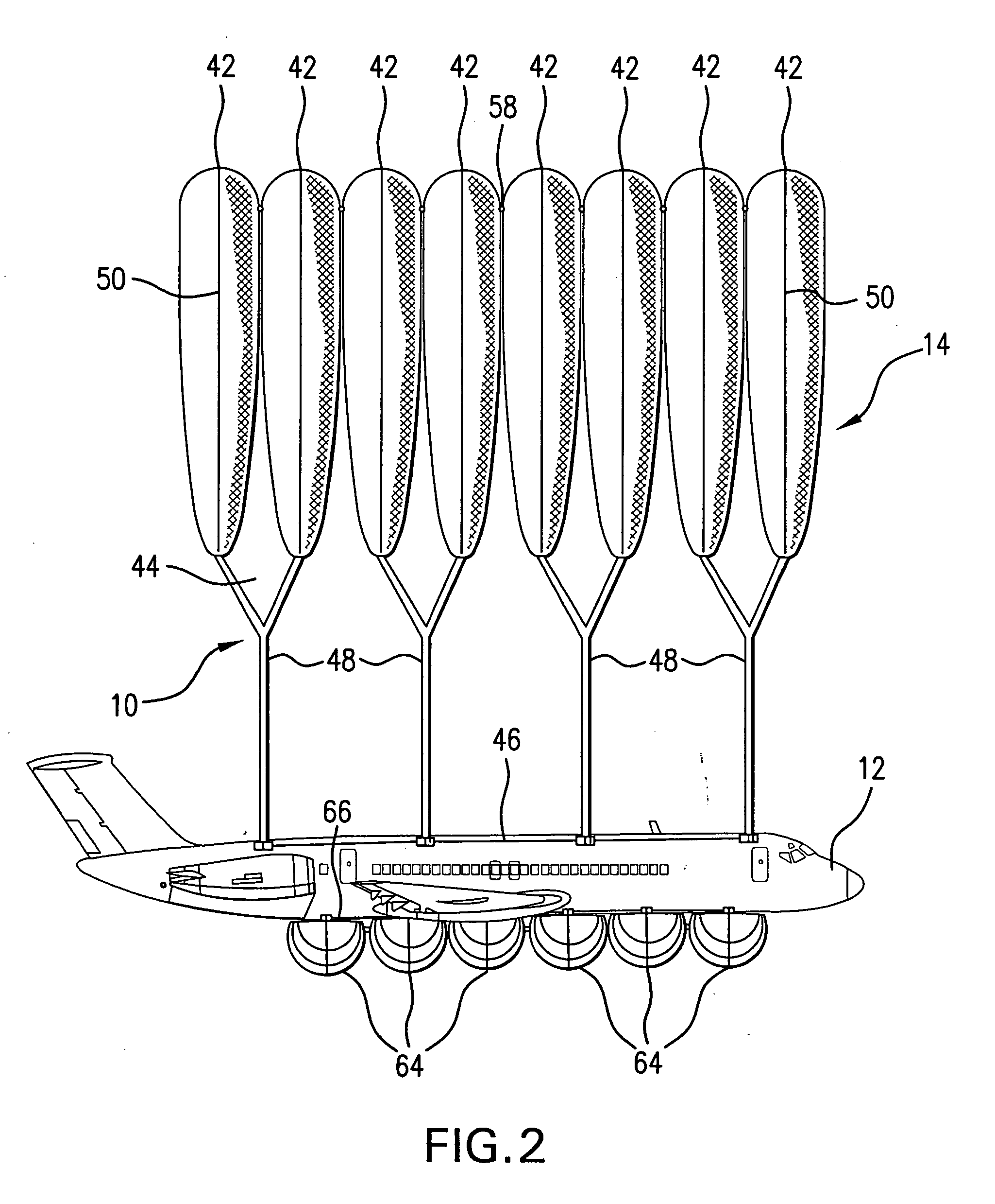
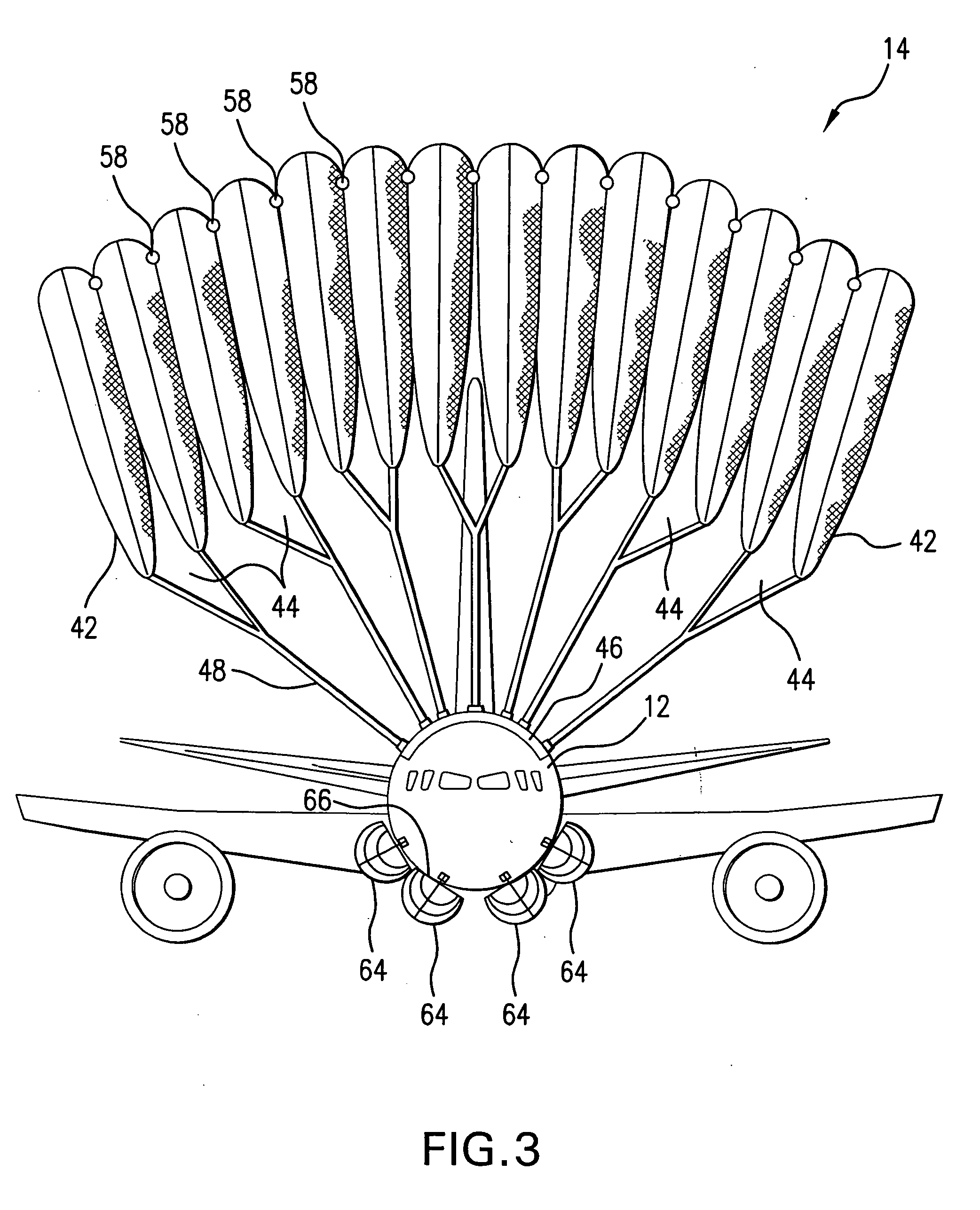
[0020] It is another object of the present invention to provide a safety landing system applicable to a variety of conveyances which when used for aircraft, combine a parachute-like structure comprised of air bags that are inflated by either air or other gases such as Helium, to control the air filled space dimension formed in the parachute-like structure in order to maintain deceleration of the vehicle within a safety range as well as to permit safe maneuvering of the vehicle.
[0021] Another object of the present invention is to provide a safety pre-impact inflatable deceleration system which uses a plurality of air bags arranged in a grid-like parachute that are deployed external the vehicle prior to an impact and which are responsively inflated / deflated to a predetermined controllable extent for providing safe deceleration rates of the vehicle. The system further has a plurality of air bags spaced adjacent the bottom and sides of the aircraft and deployable and inflatable upon detection of pre-collision situations to provide for a safe landing on both land or water. The system further provides for flotation on water when needed.

Problems solved by technology

This design is likely to create uncontrollably rapid and unwarranted deceleration that may cause injuries and possibly death of passengers.
In addition, since the escape cabin separates from the remainder of the aircraft, navigation of the aircraft may be difficult.
However, once the air bag is inflated, it begins to deflate and provides little protection from secondary impacts.
In a detailed analysis of the physics of the exterior air bags, it was found that compression of the air bags slows a vehicle at a fast and exponential rate.
Rates of deceleration exceeding 18 g's are not tolerated by humans due to its effect on the compression of vital organs, such as the brain, of the occupants of the vehicle, which may result in injuries and possibly death.
A major drawback of the design is that it may take as long as 200 milliseconds to fully inflate the airbags for an average vehicle.
However, no detailed description of the configuration of the external air bag, or the rate of deceleration, has been provided.
Existing inflatable safety devices fail to provide for a parachute structure for deceleration and buoyancy, which would have air spaces (or openings) with adjustable expansion to allow for steering during descent as well as for controlled deceleration of the vehicle in collision.
In addition, the existing inflatable safety devices are not inflated by helium or another light gas, nor do they use rapid sequence film cameras to document the events surrounding the collision.
Prior art fails to teach the triggering of the cameras by imminent air bag deployment.

Method used


Image

  • Safety pre-impact deceleration system for vehicles
  • Safety pre-impact deceleration system for vehicles
  • Safety pre-impact deceleration system for vehicles

Examples


Embodiment Construction

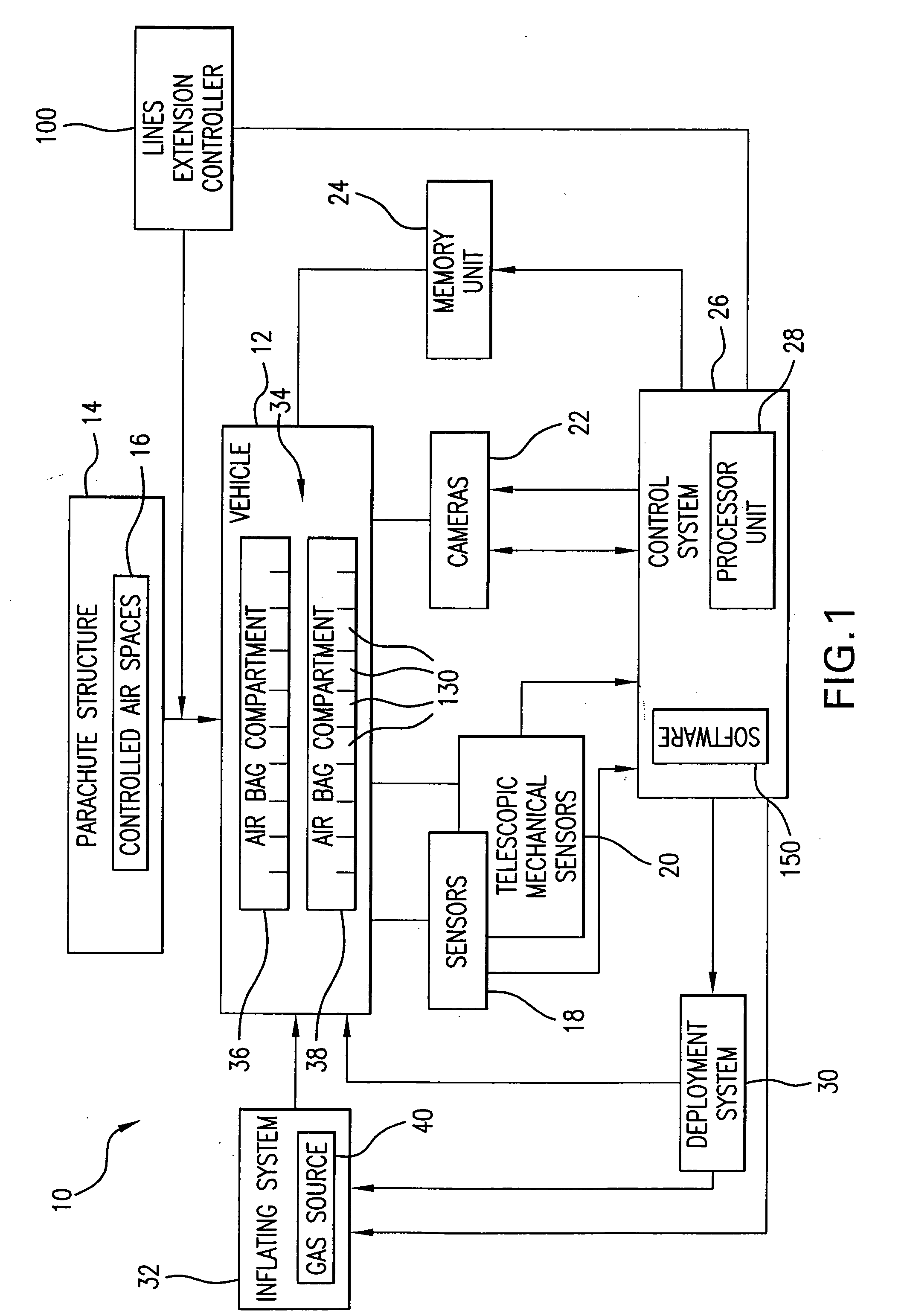
[0072] Referring to FIG. 1, a pre-impact safety deceleration system 10 of the present invention is installed on a vehicle 12 which in general may be a variety of conveyances, including aircraft, watercraft, as well as land vehicles. System 10 includes a parachute structure 14 which in the normal state of operation of the vehicle is positioned in a parachute compartment in the vehicle, which is deployed once an abnormal, e.g., pre-collision situation is detected. The parachute structure 14 is envisioned in several alternative forms which will be described further herein.

[0073] All of the embodiments of the parachute structure 14 of the present invention are designed to provide enhanced control of a vehicle's landing. Enhanced control is attained by controlling in a selective manner the expansion / contraction of one or a plurality of air openings (or air spaces, or orifices) 16 formed in the parachute structure 14. The directed controlled air opening(s) expansion controls the decelera...


PUM


Abstract

A safety pre-impact deceleration system for a variety of conveyances includes a parachute structure formed from air bags inflated with gas. Alternatively, the parachute structure includes a canopy with orifices. Air spaces in the parachute structure or orifices in the canopy have adjustable and selective dimensions to control the operational parameters of the vehicle. The system includes sensors and rapid exposure rate cameras with continuous loop recording to measure operational parameters of the vehicle and to predict possible collision. Once a collision condition is detected, audio / video images are stored on storage media. The air bags are deployed and inflated. In addition to air bags constituting the parachute structure, a plurality of air bags are provided to be deployed external the vehicle to aid in a safe landing.

Description

FIELD OF THE INVENTION [0001] The present invention relates to a method and system for protecting both passengers and a vehicle when in a collision. In particular, the present invention relates to a parachute structure having a variable air resistance for a vehicle in motion or in a free fall condition. The system aids in controlling the deceleration as well as steering of the vehicle. [0002] In overall concept, the present invention relates to a pre-impact safety deceleration system which includes a parachute or parachute-like structure with opening(s) or air spaces formed therein which are controllably dimensioned for enhancing the maneuverability of a vehicle once a pre-collision situation is detected. [0003] The present invention also relates to a parachute-like structure which includes a plurality of inflatable airbags arranged in a grid-like structure which are inflated gradually in simultaneous or sequential manner once the deceleration of the vehicle deviates from a predeter...

Claims


Application Information

Patent Timeline
Patent Type & Authority Applications(United States)
IPC IPC(8): B64D17/00
CPCB64D17/80B64D25/08B64D2201/00
Inventor HAKKI, A-HAMIDHAKKI, SAMHAKKY, SAID I.
Owner HAKKI A HAMID
Why Eureka
Eureka Blog
Learn More