Power amplifier unit, communication terminal and control method of power amplifier unit

Inactive Publication Date: 2007-06-28
MITSUBISHI ELECTRIC CORP +1
View PDF1 Cites 71 Cited by
  • Summary
  • Abstract
  • Description
  • Claims
  • Application Information

AI Technical Summary

Benefits of technology

[0006] The present invention has been made to solve the problem above, and an object of the present invention is to obtain a power-suppl

Problems solved by technology

However, in the power-supply voltage controller device disclosed in Patent Document 1, the DC/DC converter has relatively large resistance value and therefore causes large voltage drop in high-

Method used


Image

  • Power amplifier unit, communication terminal and control method of power amplifier unit
  • Power amplifier unit, communication terminal and control method of power amplifier unit
  • Power amplifier unit, communication terminal and control method of power amplifier unit

Examples


first embodiment

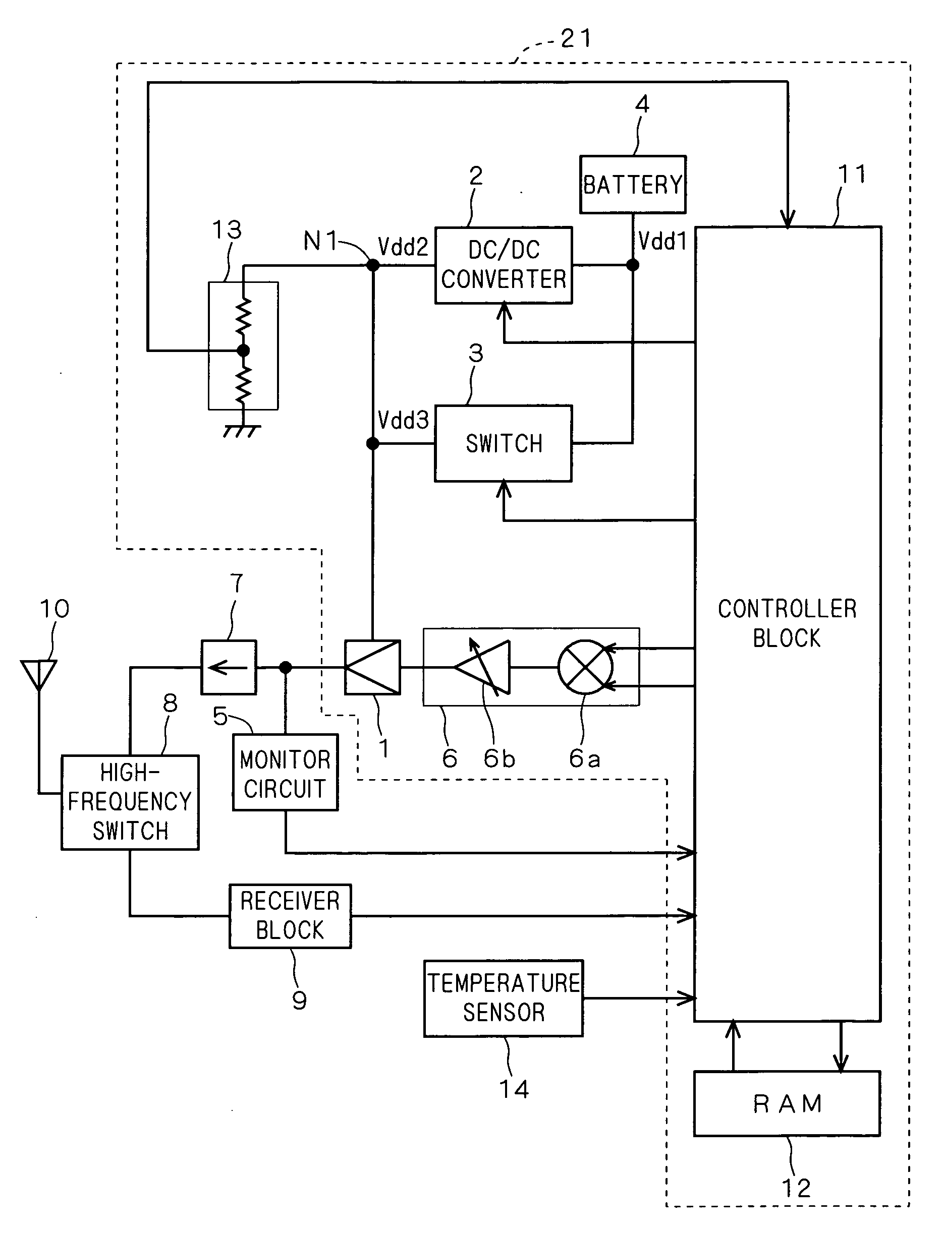
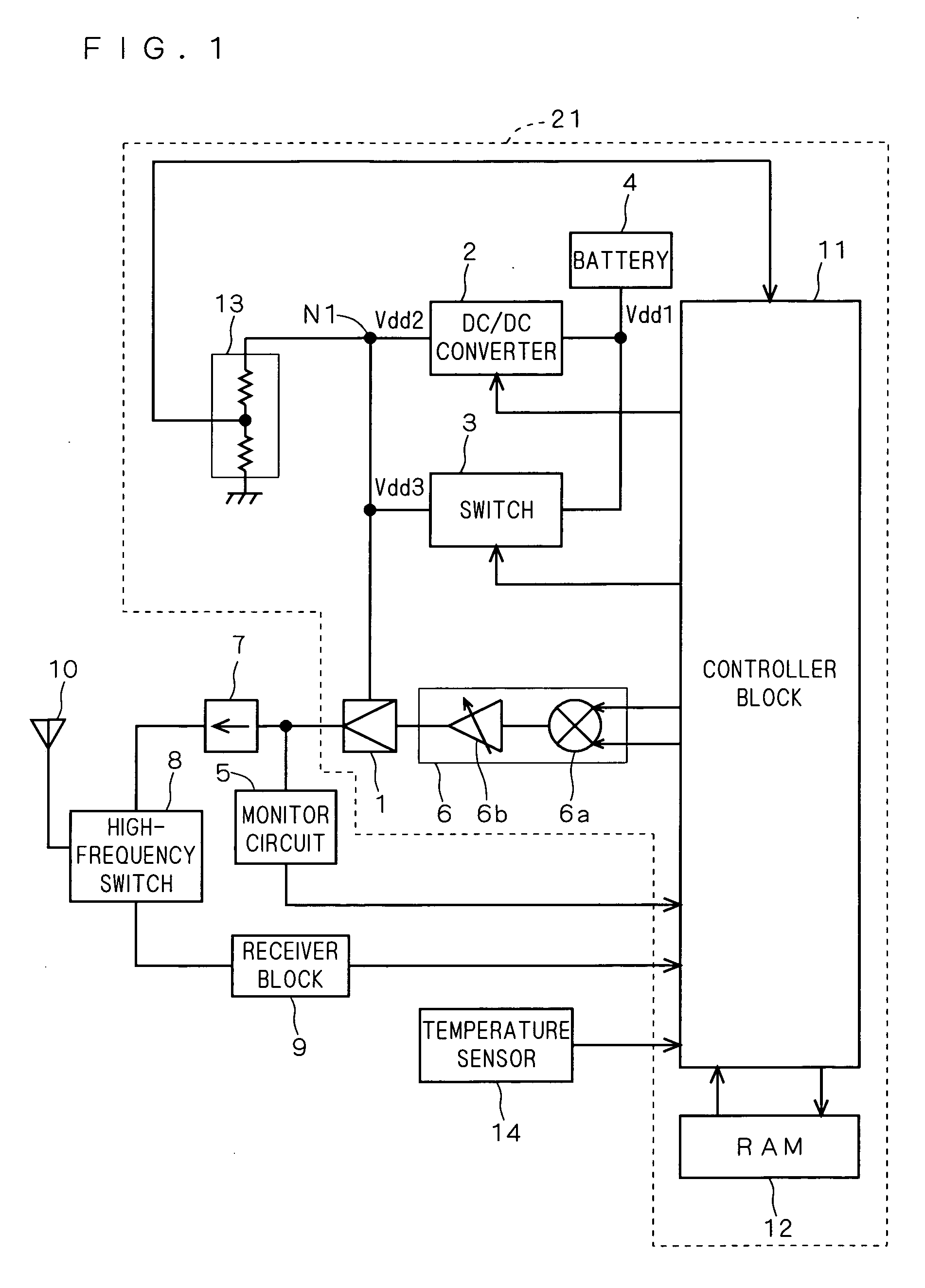
[0021]FIG. 1 is a block diagram showing the structure of a communication terminal device, e.g., a mobile phone, that includes a power amplifier device according to a first embodiment of the present invention.

[0022] As shown in the diagram, an HPA (High Power Amplifier) 1, serving as a power amplifier, amplifies a high-frequency signal (transmission signal) provided from a transmitter block 6, and sends the obtained amplified high-frequency signal through an isolator 7, a high-frequency switch 8, and an antenna 10. The isolator 7 is provided to reduce power reflected from the antenna 10 to allow stable operation of the HPA 1, and the high-frequency switch 8 is provided to determine the signal route from the transmitter block 6 to the antenna 10 during transmission and the signal route from the antenna 10 to the receiver block 9 during reception. The high-frequency switch 8 functions also as a duplexer to block the signal coming along the route from the transmitter block 6 to the rec...

second embodiment

[0081]FIG. 6 is a block diagram showing the structure of a communication terminal device having a power amplifier device according to a second embodiment of the present invention.

[0082] As shown in the diagram, the operating power-supply voltage detecting circuit 13 of the first embodiment is replaced by an operating power-supply voltage detecting circuit 15, which detects the power-supply voltage Vdd1 at a node N2 from the battery 4 and provides the obtained detected power-supply voltage value VM to the controller block 11.

[0083] Accordingly, a power amplifier device 22 is formed by the HPA 1, DC / DC converter 2, switch 3, battery 4, transmitter block 6, controller block 11, RAM 12, and operating power-supply voltage detecting circuit 15. The portion of the power amplifier device 22 excluding the HPA 1, transmitter block 6, and operating power-supply voltage detecting circuit 15 functions as a power-supply voltage supplying portion. In other respects, the structure is the same as ...


PUM


Abstract

The present invention relates to a power amplifier device having a power amplifier, and an object of the invention is to enable efficient use of the power amplifier without causing any problems in the operation of the power amplifier.
In order to achieve the object, a controller block 11 judges on the basis of an estimative output power value whether a power amplifier is in a first period in which it performs low power output operation or in a second period in which it performs high power output operation, where, in the first period, the controller block 11 activates a DC/DC converter 2 to supply a power-supply voltage Vdd2 as the operating power-supply voltage to the HPA 1, and in the second period, the controller block 11 controls the DC/DC converter 2 between active and inactive states and a switch 3 between on and off states on the basis of a detected power-supply voltage value VM obtained from an operating power-supply voltage detecting circuit 13, so as to supply one of the power-supply voltage Vdd2 and a power-supply voltage Vdd3 as the operating power-supply voltage.

Description

TECHNICAL FIELD [0001] The present invention relates to a power amplifier device having a power amplifier and controlling the operating power-supply voltage supplied to the power amplifier, a controlling method thereof, and a communication terminal device using the power amplifier device. BACKGROUND ART [0002] In a mobile phone (mobile communication terminal) as one of the mobile communication terminal devices, a speech signal input from the microphone is amplified in a power (speech) amplifier, superimposed on a carrier, and sent to a base station. Conventionally, such a power amplifier is supplied with power at its power-supply voltage terminal directly from a rechargeable battery, such as a lithium-ion battery, serving as the power source of the mobile communication terminal. [0003] Japanese Patent Application Laid-Open No. 2002-290247 (hereinafter referred to simply as “Patent Document 1”) discloses a power-supply voltage controller device and a mobile communication terminal hav...

Claims


Application Information

Patent Timeline
IPC IPC(8): H03F3/04H03F1/02H03F3/24H03G1/00H03G3/00H03G3/30
CPCH03F1/0255H03F3/24H03F2200/451H03F2200/504H03F2200/511H03G1/0088H03G3/004H03G3/3042
Inventor BABA, MAKOTO
Owner MITSUBISHI ELECTRIC CORP
Why Eureka
Try Eureka