Light guide and display device incorporating the same

a technology of light guide and display device, which is applied in the direction of instruments, computing, electric digital data processing, etc., can solve the problems of affecting the guiding effect, light loss at the output end, and viewing the screen brightness too bright, so as to ensure the guiding effect of light, simple structure, and increase flexibility of the disposition of the light guide on the display devi

Inactive Publication Date: 2007-06-28
AU OPTRONICS CORP
View PDF6 Cites 8 Cited by
  • Summary
  • Abstract
  • Description
  • Claims
  • Application Information

AI Technical Summary

Benefits of technology

[0009]It is therefore an object of the invention to provide a light guide and display device incorporating the same. Through restrictions on size ratio and the surface design of an irregular structure, the light guide assures the guiding effect of the light even when the incident angle of a light beam is large. With a simple structure, the flexibility of the disposition of the light guide on the display device is increased, and the manufacturing cost is reduced.
[0010]The invention achieves the above-identified object by providing a light guide. The light guide includes a first surface, a second surface and a lateral surface. The first surface is for receiving a light beam. The second surface is for guiding the light beam and is opposite to the first surface. The second surface has an irregular structure for reducing a luminous flux of a total reflection of the light beam projected on the second surface. The lateral surface is for connecting the edges of the first surface and the second surface. Meanwhile, the luminous flux of the light beam from the first surface to the second surface is larger than the luminous flux of the light beam from the first surface to the lateral surface.
[0011]The invention further achieves the above-identified object by providing a display device. The display device includes a housing, a screen, a light guide, a light sensor and a controlling circuit. The screen is disposed on the front surface of the housing. The light guide is used for guiding a light beam. The light guide includes a first surface, a second surface and a lateral surface. The first surface is for receiving the light beam. The first surface is disposed on the front surface of the housing. The second surface is for guiding the light beam and is opposite to the first surface. The second surface has an irregular structure for reducing a luminous flux of a total reflection of the light beam projected on the second surface. The lateral surface is for connecting the edges of the first surface and the second surface, meanwhile the luminous flux of the light beam from the first surface to the second surface is larger than the luminous flux of the light beam reflected from the first surface and projected onto the lateral surface. The light sensor disposed inside the housing and opposite to the second surface is for receiving a light beam guided by the second surface and outputting a signal accordingly. The controlling circuit couples the screen and the light sensor, and adjusts the screen brightness according to the signal.

Problems solved by technology

For example, when watching the TV at a dark room or in the night time, the viewer might feel that the screen brightness is too Bright.
To the contrary, when watching the TV at a well-illuminated room or in the day time, the viewer might feel that the screen brightness is too dark.
Otherwise, when the light beam is projected onto the wall of the light pipe, the incident angle is unable to achieve the critical angle above which total reflection occurs and part of the light beam will be refracted from the light pipe, resulting in a light loss at the output end and affecting the guiding effect.

Method used


Image

  • Light guide and display device incorporating the same
  • Light guide and display device incorporating the same
  • Light guide and display device incorporating the same

Examples


Embodiment Construction

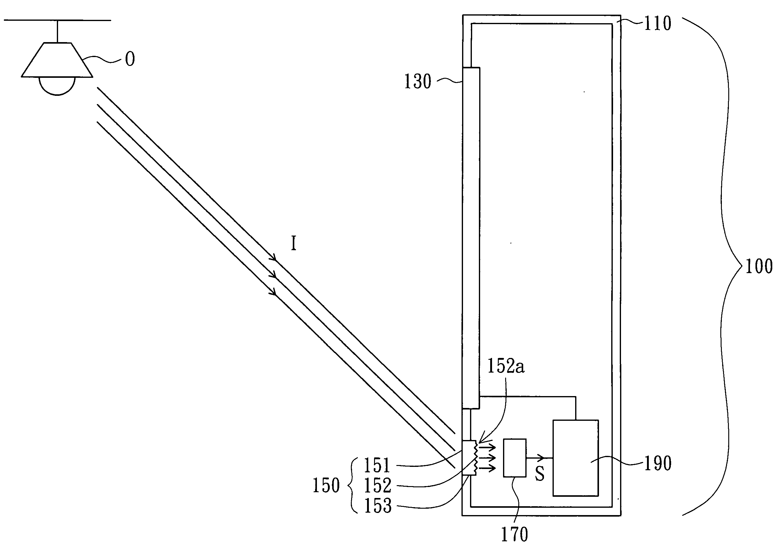
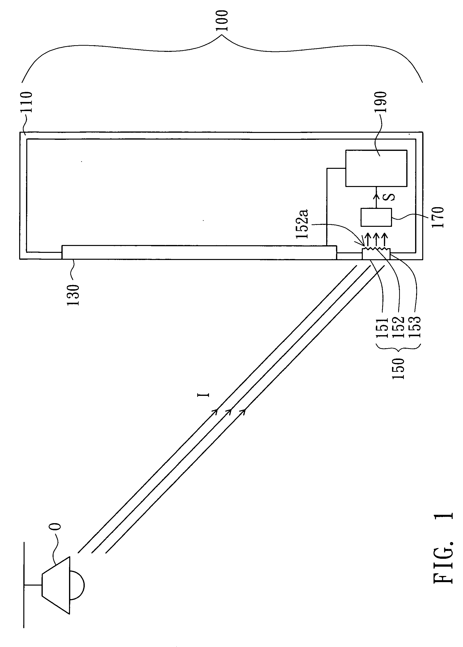
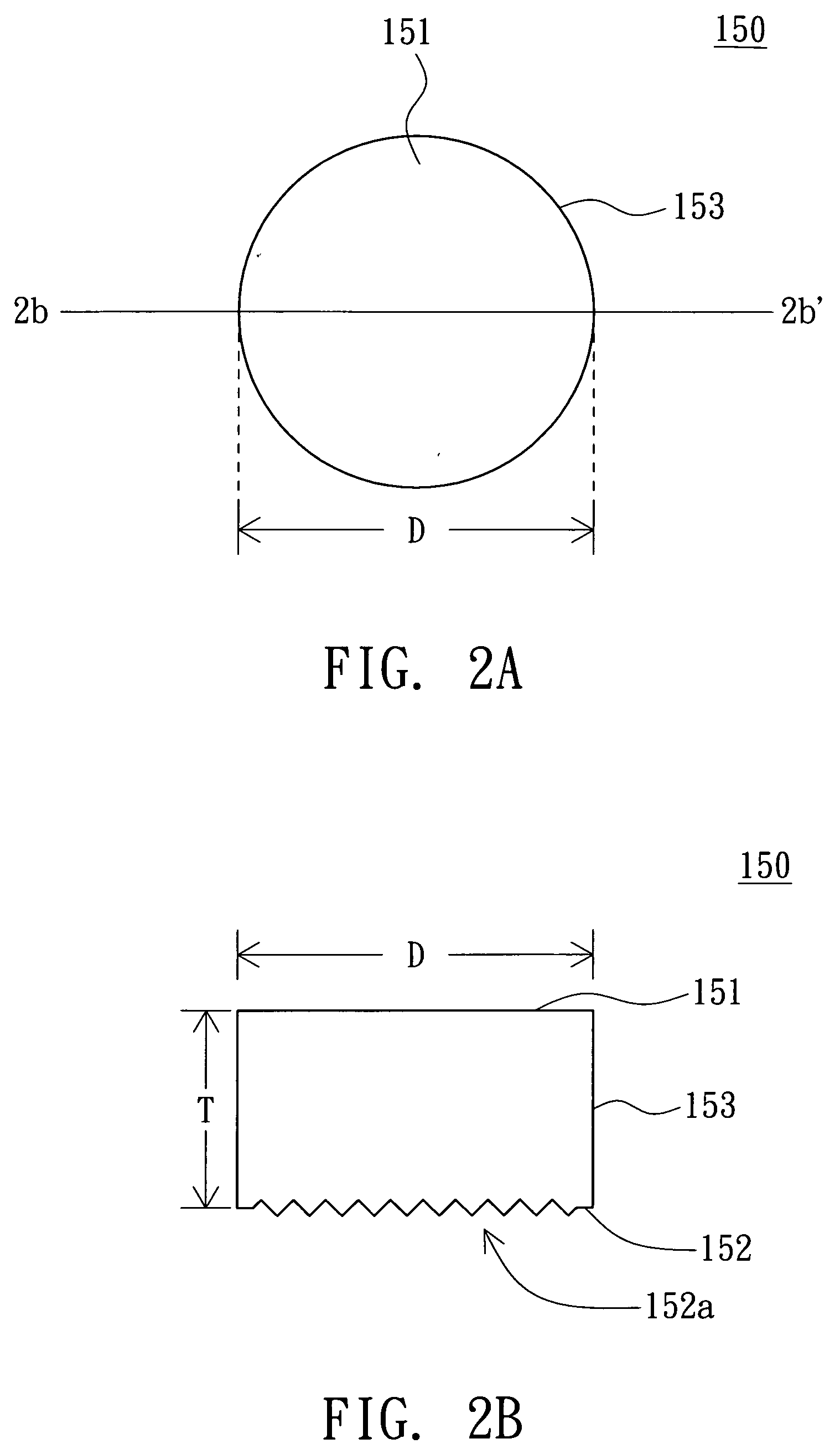
[0017]Referring to FIG. 1, a diagram of a display device adjusting screen brightness by environmental brightness according to a preferred embodiment of the invention is shown. The display device 100, such as a liquid crystal TV or a plasma TV, includes a housing 110, a screen 130, a light guide 150, a light sensor 170 and a controlling circuit 190. The screen 130 is disposed on the front surface of the housing 110. The light guide 150 can be made from a transparent material, such as poly methyl methacrylate (PMMA), MS resin, poly carbonate (PC) and polyethylene terephthalate (PET) and so on. The light guide 150 is for receiving and guiding a light beam l emitted by a light source O. The light guide 150 includes a first surface 151, a second surface 152 and a lateral surface 153.

[0018]The first surface 151 used for receiving the light beam l is disposed on the front surface of the housing 110. The second surface 152 used for guiding the light beam l is opposite to the first surface 1...


PUM


Abstract

A light guide and a display device incorporating the same are provided. The light guide includes a first surface, a second surface and a lateral surface. The first surface is for receiving a light beam. The second surface is for guiding the light beam and is opposite to the first surface. The second surface has an irregular structure for reducing a luminous flux of a total reflection of the light beam projected on the second surface. The lateral surface is for connecting the edges of the first surface and the second surface. Meanwhile, the luminous flux of the light beam from the first surface to the second surface is larger than the luminous flux of the light beam from the first surface to the lateral surface.

Description

[0001]This application claims the benefit of Taiwan application Serial No. 9414702, filed Dec. 28, 2005, the subject matter of which is incorporated herein by reference.BACKGROUND OF THE INVENTION[0002]1. Field of the Invention[0003]The invention relates in general to a light guide and a display device incorporating the same, and more particularly to a light guide and a display device incorporating the same with restriction on size ratio and an irregularly structured surface.[0004]2. Description of the Related Art[0005]The display brightness of the frame of an ordinary display device such as liquid crystal TV can be manually adjusted by the user to fit into the environmental brightness. For example, when watching the TV at a dark room or in the night time, the viewer might feel that the screen brightness is too Bright. To the contrary, when watching the TV at a well-illuminated room or in the day time, the viewer might feel that the screen brightness is too dark. Apart from the conv...

Claims


Application Information

Patent Timeline
Patent Type & Authority Applications(United States)
IPC IPC(8): G09G5/00
CPCG02B6/0008G02F1/13318
Inventor HSU, CHIEN-CHIANG
Owner AU OPTRONICS CORP
Why Eureka
Try Eureka