
Liquid discharge method, liquid discharge head and liquid discharge apparatus

a liquid discharge head and liquid discharge technology, applied in printing and other directions, can solve the problems of increasing the quantity of liquid discharged by the inertial force, affecting the image quality, etc., and achieve the effect of reducing satellites and mists

Active Publication Date: 2007-06-28
CANON KK
View PDF9 Cites 30 Cited by
  • Summary
  • Abstract
  • Description
  • Claims
  • Application Information

AI Technical Summary

Benefits of technology

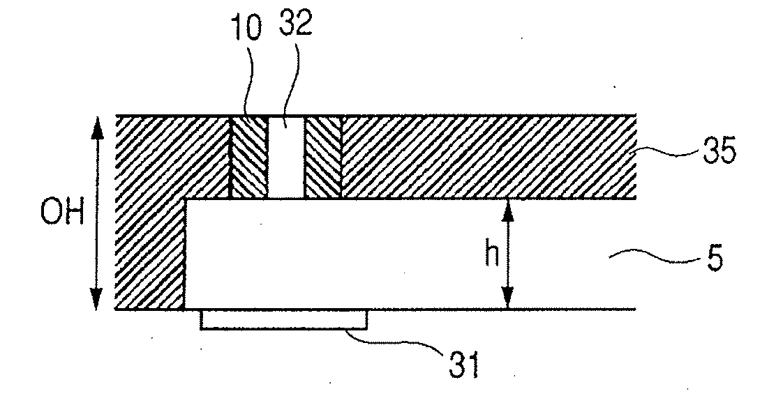
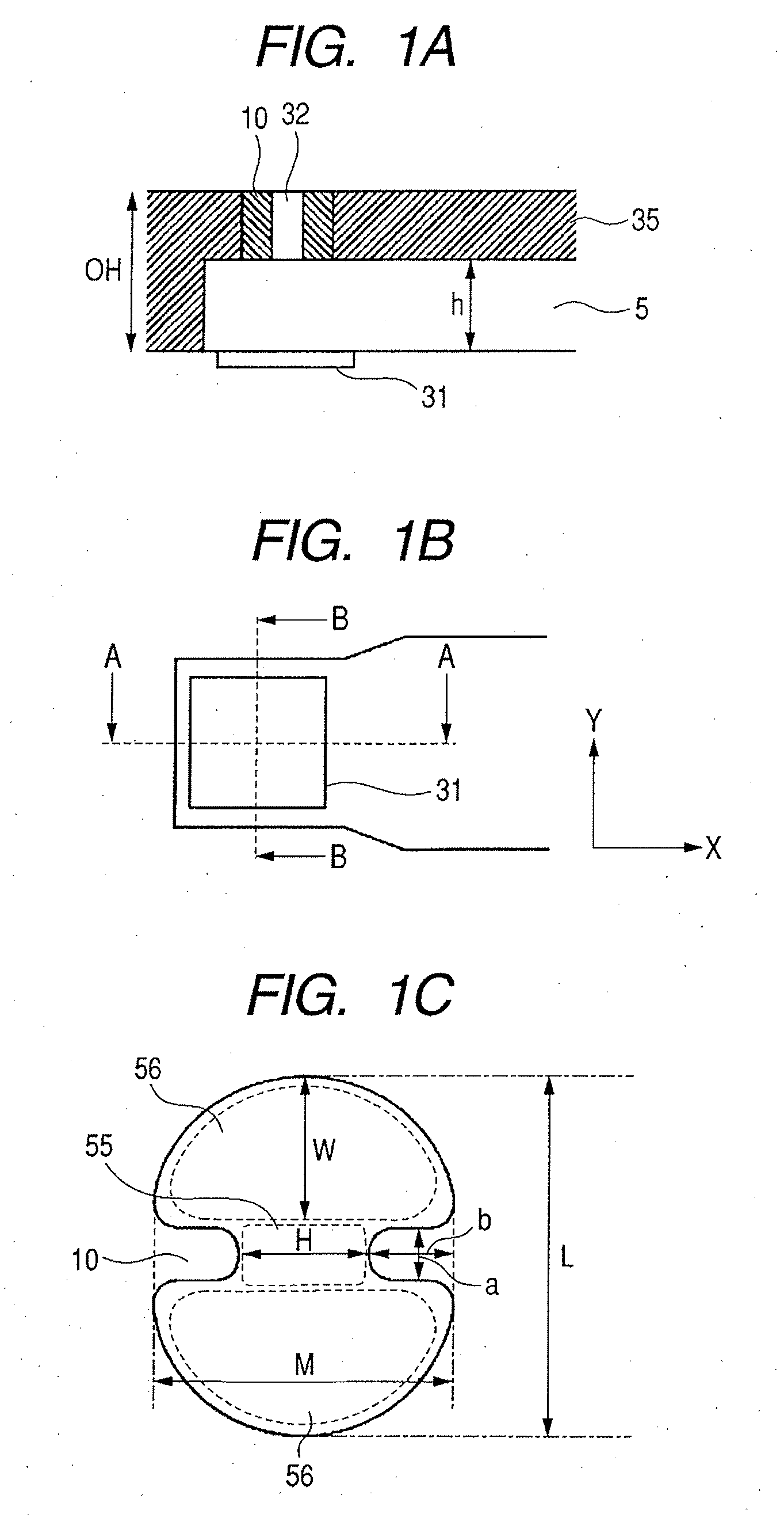
[0076] Additionally, as shown in the cross-sectional view in FIG. 1A, it is preferable that the central axis of the discharge port portion in the liquid discharge direction be perpendicular to the surface of the discharge port and the energy generating element, because of the symmetries of the positions of the meniscus and the stability of discharging. In the case wherein the central axis of the discharge port portion is not perpendicular to the surface of the discharge port or the heat generating element, at the bubble fading stage at which the meniscus position in the discharge port portion is moved toward the heat generating element, asymmetries for the meniscus positions are remarkable, and the effects of the invention can not be sufficiently obtained.
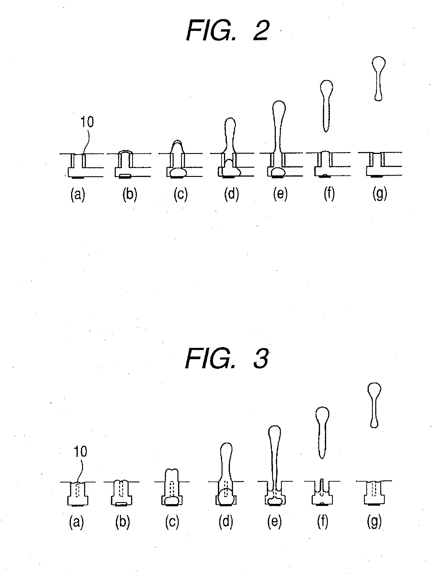
[0077]FIGS. 18A, 18B, 19A and 19B show the shapes of projections for comparison examples. A discharge port in FIG. 18A is a form provided by connecting two circles. The long side of the discharge port is defined as 20.0 μm, and the short side is defined as 4.5 μm. For a projection area X indicated by a broken lined quadrilateral in FIG. 18A, x1 (direction toward the center of a discharge port) is regarded as 2.9 μm, and x2 (width of the projection root) is regarded as 9.8 μm. x2 / x1=3.4. A discharging simulation is shown in FIG. 18B, which corresponds to the interval between (e) and (f) in FIG. 3, or (e) and (f) in FIG. 14. While referring to FIG. 18B, before a liquid pillar is separated from a liquid in a discharge port, holding of a liquid between the projections begins to be broken, and a portion of the liquid pillar to be cut is dropped to the heater side in the discharge port. Therefore, the length of the tail of a liquid droplet to be discharged is not as short as in the shape provided by the embodiment, and this causes the occurrence of satellites.
[0078] This is because of the following reasons. Since the projections in FIG. 18B are abruptly sharpened close to the distal ends, and the shapes of the distal ends are pointed, a force different from that in the embodiment is exerted to the meniscus when a bubble is faded and the liquid in the discharge port is taken in to the heater side. During fading of a bubble, ink moves to the heater side slowly as it is close to the inner wall of the discharge port. Thus, as indicated by a shaded portion in FIG. 21A, the liquid remains along inside the discharge port, and indicated by a white portion, a force is exerted in the center of the discharge port to drop the meniscus in a form like connecting two circles. Thus, the liquid between the projections is pulled in to the heater side, and it is difficult that the liquid is held between the projections.
[0079] On the other hand, for a discharge port shown in FIG. 19A, the shape of projections is very blunted. The long side of the discharge port is defined as 20.6 μm, and the short side is defined as 7.7 μm. For a projection area X indicated by a broken lined quadrilateral in FIG. 19A, x1 (direction toward the center of a discharge port) is regarded as 2.2 μm, and x2 (width of the projection root) is regarded as 8.2 μm. x2 / x1=3.7. A simulation for this is shown in FIG. 19B, which corresponds to the interval between (e) and (f) in FIG. 3, or (e) and (f) in FIG. 14. In FIG. 19B as well as in FIG. 18B, before a liquid pillar is separated from a liquid in the discharge port, holding of the liquid between the projections begins to break down, and the portion of the liquid pillar to be cut is dropped to the heater side in the discharge port. Thus, the length of the tail of a liquid droplet to be discharged does not become as short as the shape provided by the embodiment, and this causes the occurrence of satellites.
[0080] This is because, when a bubble is faded and the liquid in the discharge port is pulled in to the heater side, a force different from that in the embodiment is exerted to the meniscus. Since the projections in FIG. 19B are very blunted, there is almost no difference between the high fluid resistant portion that holds a liquid and the low fluid resistant portions that drop the meniscus to the heater side. Thus, during bubble fading, as indicated by the hatched portion in FIG. 21B, the liquid remains along the inner wall of the discharge port, and as indicated by the white portion, a force to pull the liquid to the heater side is exerted in the center portion of the discharge port, so that it is difficult that the liquid is held between the projections. Other Shapes of Discharge Ports Applicable for the Present Invention
[0081] Next, in this embodiment, examples viewed from a direction perpendicular to a heater face are shown in FIGS. 15, 16A and 16B. The head structure in FIG. 15 is the shape wherein projections are formed for a two-step discharge port. A first discharge port 5 is formed to communicate with a flow path 5 above a heater; a second discharge port 6 smaller than the first discharge port is formed above the first discharge port 5; and projections 10 are formed on the second discharge port 6. Since the first discharge port is large, clogging of a liquid to be discharged can be suppressed, and a tiny liquid droplet can be formed through the second discharge port. Furthermore, the tail of a discharged liquid can be reduced at the projections of the second discharge port, and in addition, since the first discharge port portion having a small resistance is included, the discharge efficiency is improved. Further, since the forward resistance of the nozzle is reduced, a bubble easily grows upward in the discharge port, and during bubble fading, a meniscus can be pulled in the nozzle with a great force, so that the state wherein a liquid film is extended between the projections can be prepared earlier, and separation time for a liquid droplet is advanced.

Problems solved by technology

Furthermore, the inertial force also increases the quantity of the liquid that is discharged.
This results in the degradation of the image quality.

Method used


Image

  • Liquid discharge method, liquid discharge head and liquid discharge apparatus
  • Liquid discharge method, liquid discharge head and liquid discharge apparatus
  • Liquid discharge method, liquid discharge head and liquid discharge apparatus

Examples


embodiment 2

Comparison Example 2

[0094] In Table 2, results obtained under the same conditions as in embodiment 1 described above are shown, except for the structure (the diameter of a discharge port, flow paths, an OH distance and projection shapes) of a head. Embodiment 2-1 is an example wherein projections are inserted between semi-circular portions of a diameter of 11 μm, as shown in FIG. 17, and the relationship between M, L and H and the values in the table is the same as that for embodiment 1. In this embodiment, x2 / x1=1.35 and x1≧x2, and the discharge quantity is 1.7 ng. Comparison example 2 employs a circular discharge port of a diameter of 11 μm, and the discharge quantity is 1.5 ng. According to the head having projections in this embodiment, the liquid separation time was advanced, compared with the circular one in comparison example. Further, it could be confirmed that the discharged liquid droplet was shortened, and the number of satellites was reduced. Additionally, the number of...

embodiment 3

Comparison Example 3

[0095] In Table 3, results obtained under the same conditions as in embodiment 2 described above are shown, except for the structure (the diameter of a discharge port, flow paths, an OH distance and projection shapes) of a head.

[0096] Embodiments 3-1 to 3-5 are examples wherein projections of sizes written in the table are inserted between semi-circular portions of a diameter of 11 μm, as shown in FIG. 17, and the relationship between M, L and H and the values in the table is the same as that for embodiment 1. In these embodiments, the discharge quantity is 1.7 ng. In the range of 1.6≧x2 / x1, as shown in embodiments 3-1 to 3-5, a small number of satellites was obtained as a result. Comparison example 3-1 employs a circular discharge port having a diameter of 11 μm, and the discharge quantity is 1.6 ng. Comparison example 3-2 employs the shape wherein projections of a length 0.7 are inserted between semi-circular portions of a diameter of 11 μm, and the discharge...

embodiment 4

Comparison Example 4

[0097] In Table 4, results obtained under the same conditions as in embodiment 3 described above are shown, except in that the diameter of a discharge port was increased more.

[0098] Embodiment 4 is an example wherein projections of sizes written in the table are inserted between semi-circular portions of a diameter of 13 μm, as shown in FIG. 17, and the relationship between M, L and H and the values in the table is the same as that for embodiment 1. In this embodiment, x2 / x1=0.8 and x1≧x2. The discharge quantity is 2.3 ng. Comparison example 4 employs a circular discharge port having a diameter of 13 μm and the discharge quantity is 2.3 ng. According to this, for the head in this embodiment that has projections, it was confirmed that, compared with the circular one in the comparison example, the liquid separation time was advanced, the discharged liquid droplet was shortened and the satellites were reduced. The number of particles changed as a mist was also sha...


PUM


Abstract

A liquid discharge head is arranged in a manner that in the cross section of a discharge port in a liquid discharge direction, the discharge port includes: at least one projection that is convex inside the discharge port; a first area, for holding a liquid surface connecting a pillar-shaped liquid that is elongated outside the discharge port; and second areas where a fluid resistance is lower than that in the first area so as to pull the liquid in the discharge port in a direction opposite to the liquid discharge direction; and the first area is formed in the direction in which the projection is convex, and the second areas are formed on both sides of the projection.

Description

[0001] This application is a continuation of International Application No. PCT / JP2006 / 324315 filed on Nov. 29, 2006, which claims the benefit of Japanese Patent Application No. 2005-343943 filed on Nov. 29, 2005.BACKGROUND OF THE INVENTION [0002] 1. Field of the Invention [0003] The present invention relates to a liquid discharge head that performs recording by discharging liquid droplets onto a medium, a liquid discharge apparatus, a head cartridge and a liquid discharge method. [0004] 2. Description of the Related Art [0005] As a system for discharging a liquid such as ink, a liquid discharge system (ink jet recording system) has been developed, and as a discharge energy generating element, used for discharging liquid droplets, a method that uses a heat generating element (a heater) is available. [0006]FIG. 10 is a schematic diagram showing a general discharge process, for a bubble jet (BJ) discharge system, that employs a conventional ink jet head for preventing bubbles from comm...

Claims


Application Information

Patent Timeline
Patent Type & Authority Applications(United States)
IPC IPC(8): B41J2/05
CPCB41J2/1404B41J2/1433B41J2002/14387B41J2002/14475B41J2/14024B41J2/1603B41J2/145B41J2/04573
Inventor MURAKAMI, SHUICHITAKEI, YASUNORI
Owner CANON KK
Learn More