
Operating frequency reduction for transversal fir filter

Inactive Publication Date: 2007-06-28
RAMBUS INC
View PDF4 Cites 68 Cited by
  • Summary
  • Abstract
  • Description
  • Claims
  • Application Information

AI Technical Summary

Benefits of technology

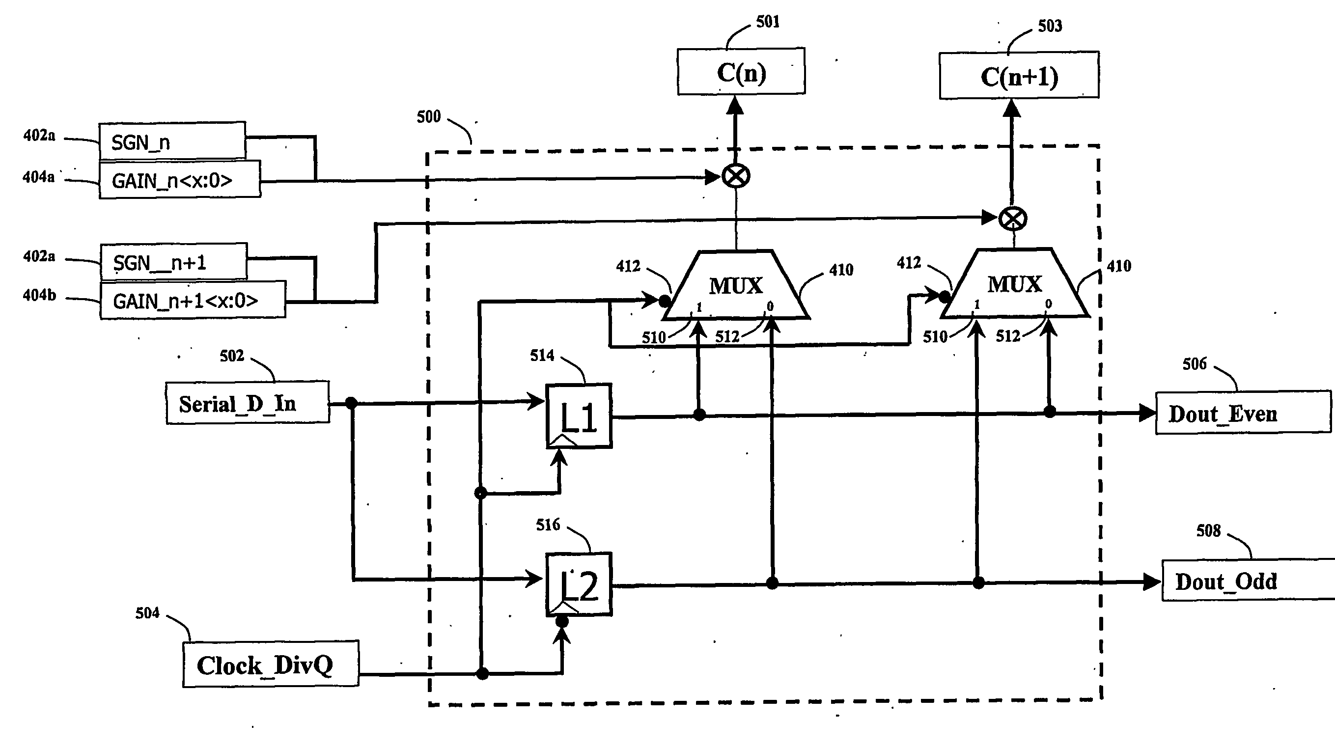
[0009] The present invention is a method and system for reducing the frequency of operation for a transversal Finite Impulse Response (FIR) filter. The transversal filter operates in such a way that it has an even and odd row of data, which are latched on rising and falling edges of the clock respectively. This allows the clock frequency to be reduced by a factor of 2, and thus allows the use of more power efficient latches. Reducing the frequency of operation causes the high speed latches within the transversal filter to hold the data bits twice as long as is required, and thus a circuit is required to select the appropriate data bits from output of the appropriate half-speed latch, and subsequently scale it to apply the co-efficient gain. Each of the subsystems is analog, and operates in accordance with a synchronous clock system
[0010] In one particular embodiment, the present invention may be characterized as a method and system to allow a transversal filter to operate at a reduced frequency while maintaining the Finite Impulse Response that is required by the application. This is achieved by providing latches that operate at a slower sub-multiple of the high speed clock and multiplexing the output of the slower latches in such a way that the co-efficient multipliers are driven by the correct data, and for the correct duration. Advantageously, the reductions in frequency for the transversal filter result in a high-speed circuit that may have considerably lower power consumption than one that operates at full speed. Additionally, the multiplexing circuit may directly apply the discreet gain required to create a coefficient, which by construction will further reduce complexity, die area, and power consumption.

Problems solved by technology

In both the case of the FFE and DFE, increasing the High Speed clock period by a factor of two would cause a functional failure.

Method used


Image

  • Operating frequency reduction for transversal fir filter
  • Operating frequency reduction for transversal fir filter
  • Operating frequency reduction for transversal fir filter

Examples


Embodiment Construction

[0021] The present invention provides a method and a system for using a double-edge clocking scheme and reducing the frequency of operation for a transversal FIR filter. The invention comprises of a set of 2:1 multiplexers, whose output amplitude can be controlled such that it is possible to apply a gain to the selected input signal. The invention is used in combination with a transversal FIR filter that operates at one half the intended data rate. The transversal filter is comprised of 2 separate sets of analog latches, where one set is positive edge active and the other set is negative edge active.

[0022] The present invention can be used to implement very high-speed transversal FIR filters where the frequency requirements may be at the very limit of some mainstream CMOS technologies and geometries. Since the frequency of operation for the latches may be reduced by a factor of 2, the overall current consumption can also be reduced, and thus an overall reduction in power consumptio...


PUM


Abstract

A method and system for reducing the frequency of operation for a transversal Finite Impulse Response (FIR) filter is disclosed. In the preferred embodiment, the transversal filter operates in such a way that it has an even and odd row of data, which are latched on rising and falling edges of the clock respectively. This allows the clock frequency to be reduced by a factor of 2, and thus allows the use of more power efficient latches. A reduction in the frequency of operation causes the high speed latches within the transversal filter to hold the data bits twice as long as is required, which changes the desired impulse response of the FIR filter. A circuit is required to select the appropriate data bits from the output of the appropriate half-speed latch, and subsequently scale it to apply the co-efficient gain. Each of the subsystems is analog, and operates in accordance with a synchronous clock system. In a more general embodiment of the invention, the data is provided to Q shift registers that operate at a clock rate which is reduced by a factor of Q.

Description

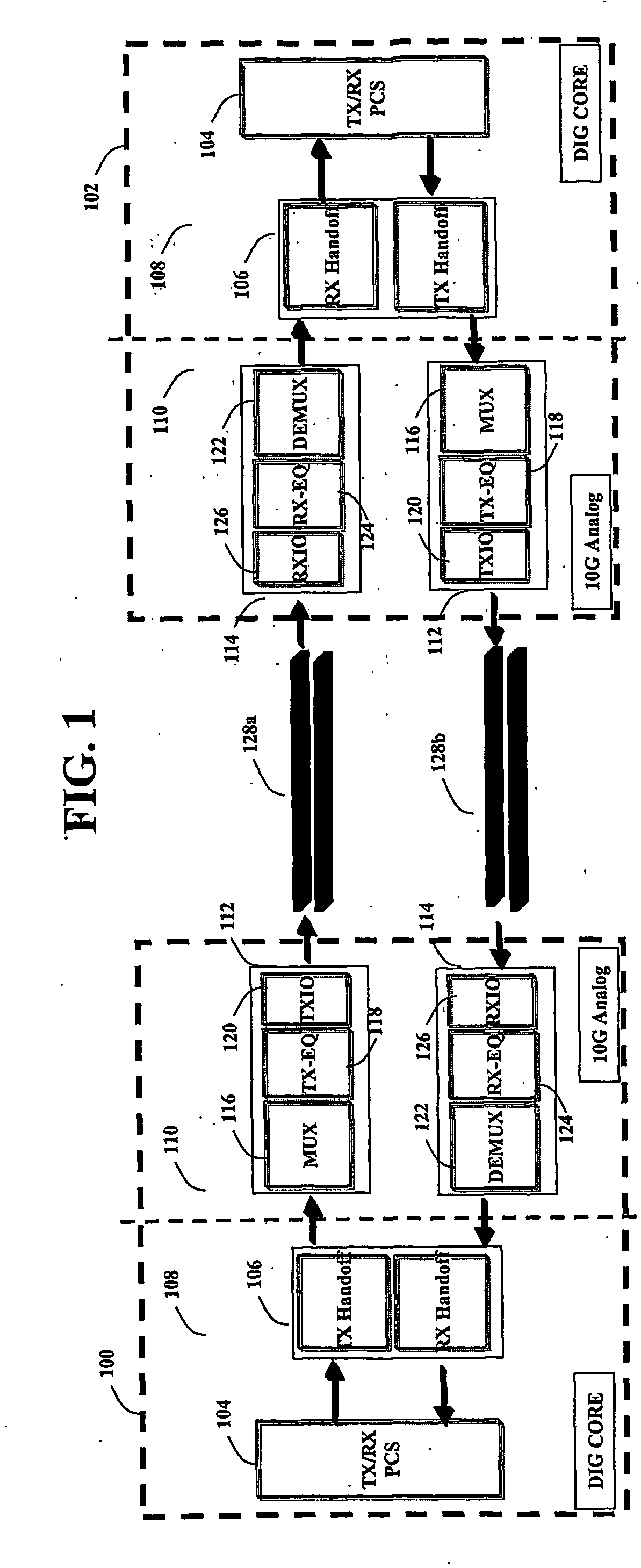
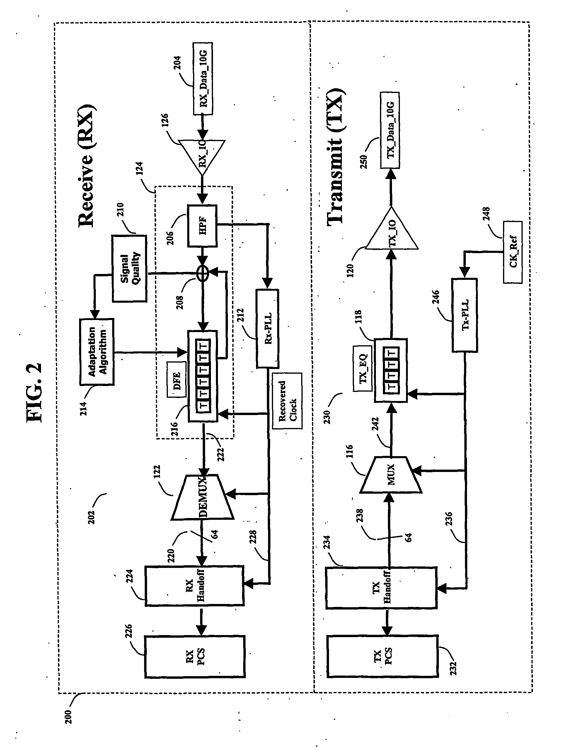
FIELD OF THE INVENTION [0001] The present invention relates generally to computer network communications and more particularly to methods and systems that allow analog transversal FIR filters to operate at ultra high frequencies. More particularly, the present invention relates to a method and a system that allows the use of double-edge clocking to reduce the frequency of operation of a transversal FIR filter whose general functionality can be used to implement a Feed Forward Equalizer (FFE) and a Decision Feedback Equalizer (DFE). The invention is particularly relevant for systems that operate at 10 Gb / s or above, where the reduction in operating frequency of a sub-block will result in reduced power consumption. BACKGROUND OF THE INVENTION Description of Related Art [0002] A standard transversal FIR filter includes a set of latches, a set of respective multiplication elements, and a summing node. The order of the filter defines that number of latches contained in the data FIFO, whe...

Claims


Application Information

Patent Timeline
IPC IPC(8): H04B1/10H03H7/30H03H17/02H03H17/06
CPCH03H17/0223H03H17/06H03H2017/0245H03H2017/0247H04L25/0278H04L25/0288H04L25/0292H04L25/03038H04L25/03057H04L25/03343H04L25/14
Inventor LAPOINTE, MARCEL
Owner RAMBUS INC
Learn More