
Method of manufacturing nanoparticles

Active Publication Date: 2007-07-05
GENERAL ELECTRIC CO
View PDF13 Cites 10 Cited by
  • Summary
  • Abstract
  • Description
  • Claims
  • Application Information

AI Technical Summary

Benefits of technology

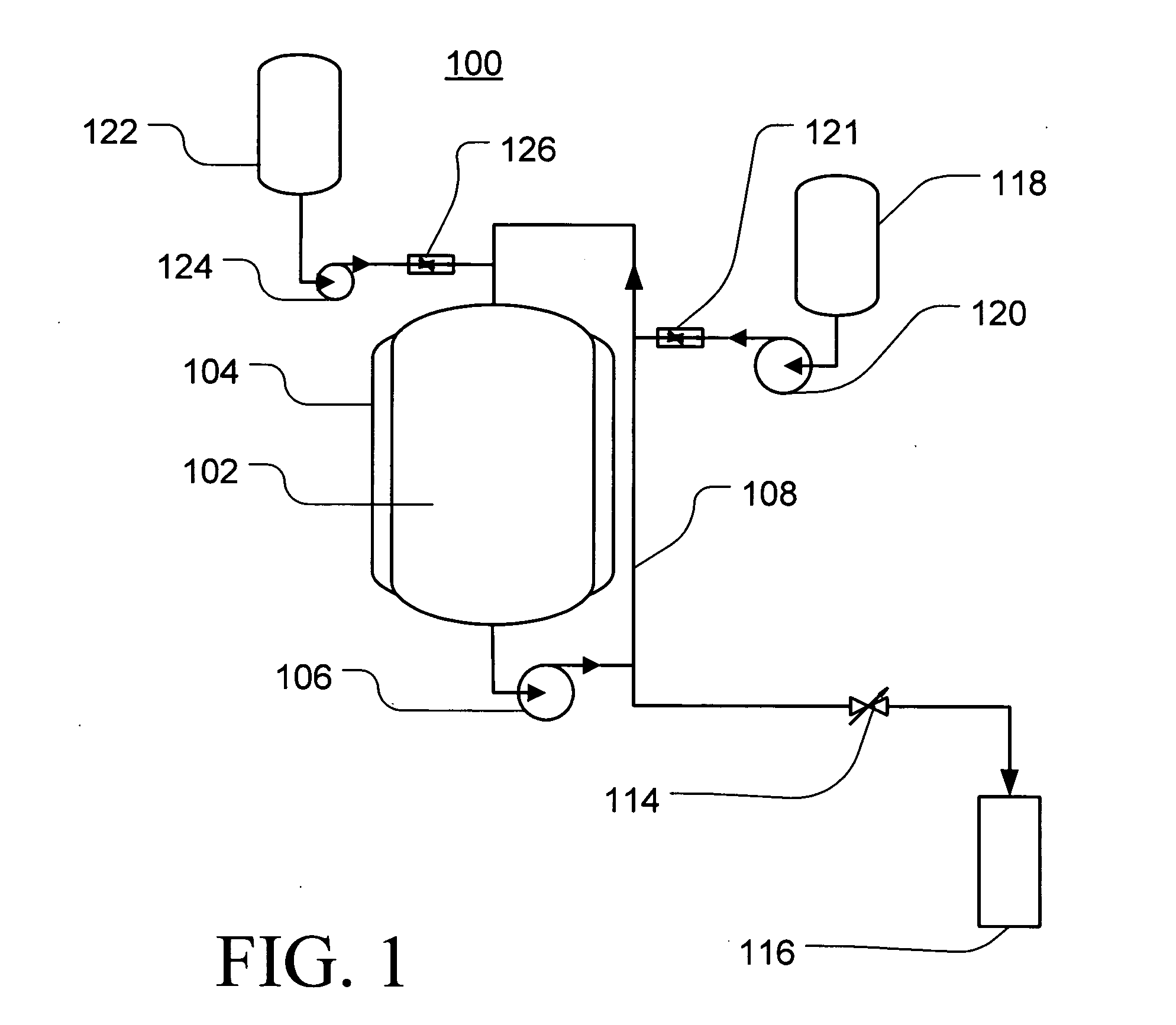
[0018] The example embodiments of methods according to the invention achieve this result without using organometallic compounds and in an aqueous medium, thereby providing methods that are generally less expensive to practice and that may also reduce the safety and environmental issues associated with the use of organic compounds, particularly when compared with conventional molecular synthesis methods.

Problems solved by technology

As suggested, however, contamination from the milling process, i.e., particles from the vessel and / or milling elements is common and the resulting nanoparticles have been known to exhibit agglomeration that can result in nanoparticle clusters having sizes in the micron range.
Secondary considerations include, for example, the tolerance of the method, the complexity of the method, the cost of the particles and environmental / safety concerns with regard to reactants required for and / or byproducts generated during operation of the method.
Agglomeration is often attributed to the action of the result of van der Waals forces between the nanoparticles and can be highly detrimental to the utilization of the nanoparticles.
These efforts, however, have been generally unsuccessful for the repeatable production of smaller, less than about 10 nm, nanoparticles.
Even when good dispersion has been achieved in a liquid phase, as the liquid is removed the likelihood of agglomeration increases.
Such control, however, often necessitates very precise control of the reaction system, thereby increasing the difficulty of the fabrication process and rendering large-scale production impractical and / or inefficient.
Further, the capital expense associated with the equipment and instrumentation necessary for successful molecular synthesis processes tends to be quite high relative to the amount of material that can be produced.

Method used


Image

  • Method of manufacturing nanoparticles
  • Method of manufacturing nanoparticles
  • Method of manufacturing nanoparticles

Examples


example

Pt Nanoparticles

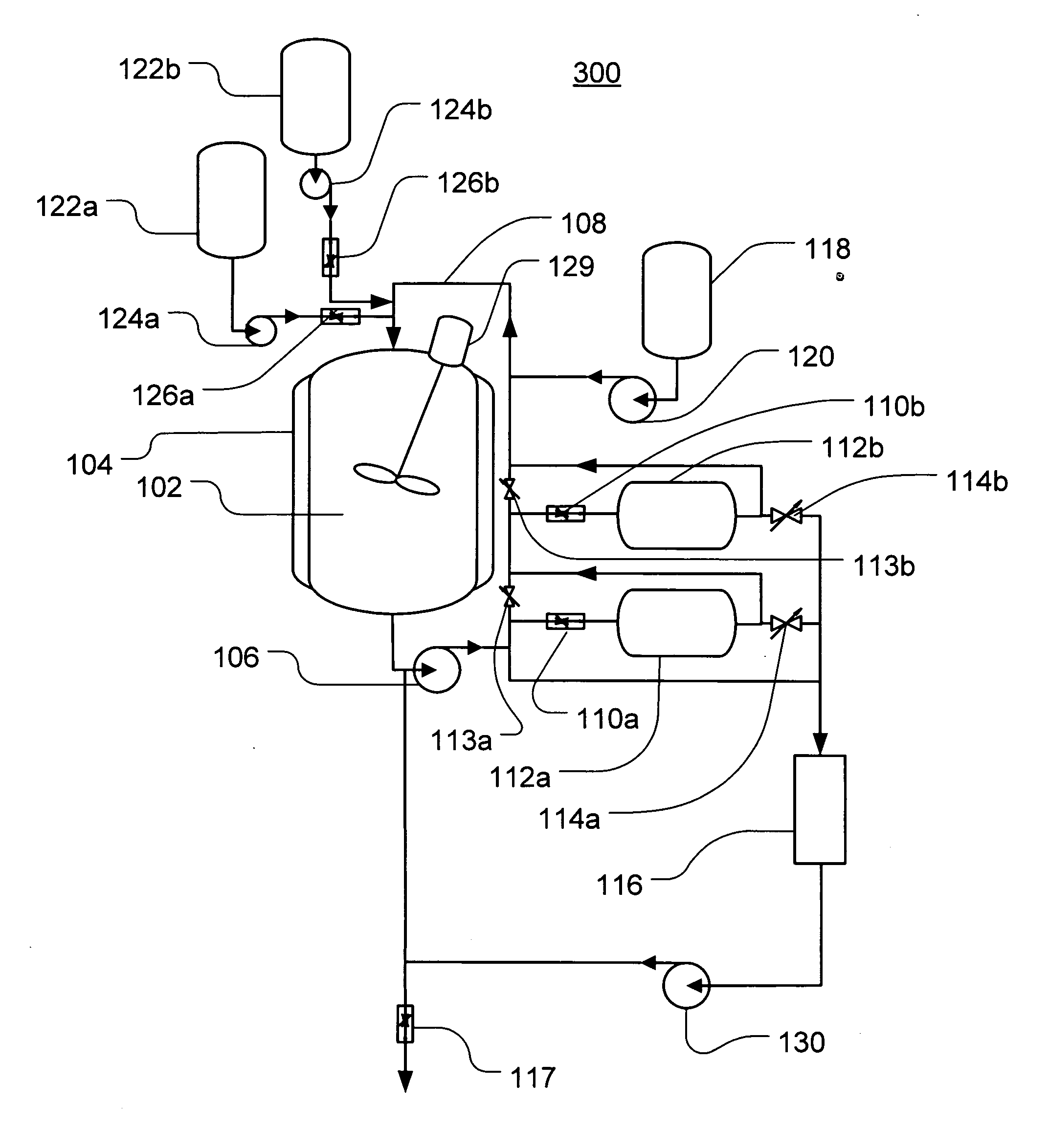
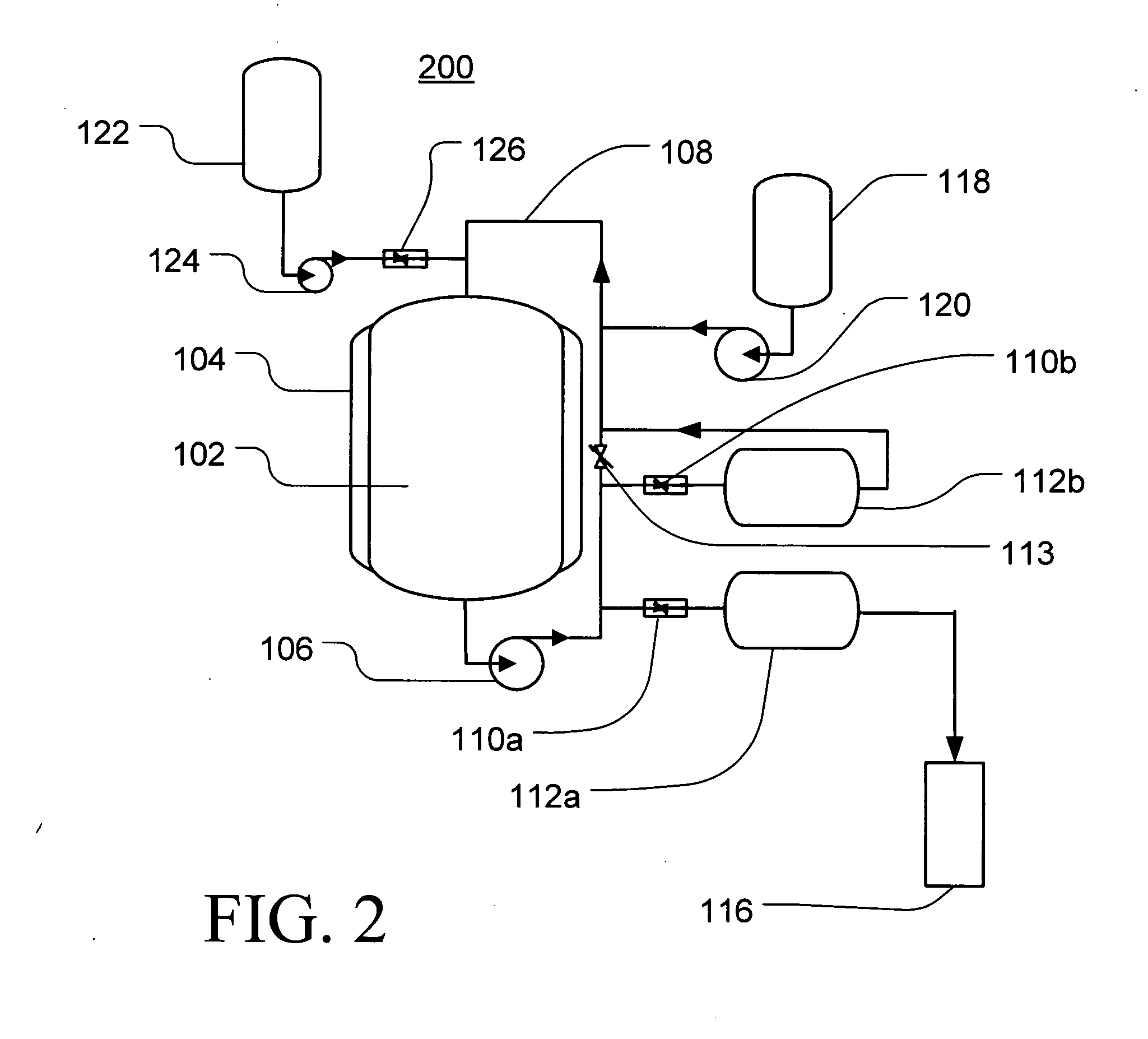
[0055] Platinum nanoparticles were generated in a reactor system generally corresponding to the example embodiment illustrated in FIG. 2 using an aqueous Pt reaction solution of Na2Pt(OH)6 at a Pt concentration of 465 ppb (by total weight). As will be appreciated by those skilled in the art, the concentration range of the chemical species can generally be controlled from, for example, about 1 ppb to several ppm, without substantial difficulties, depending on both the desired average particle size and the desired particle size distribution.

[0056] Unlike the conventional methods discussed above, the present method does not require additional organic or inorganic compounds. The concentrated chemical feed, for example a masterbatch composition, can be injected into the recirculation system at a point upstream from the main reactor vessel where the volume and turbulence of the flow is sufficient to mix and substantially dilute the concentrated chemical feed before it en...


PUM

PropertyMeasurementUnit
Temperatureaaaaaaaaaa

Abstract

Provided are methods and systems for generating nanoparticles from an inorganic precursor compound using a hydrothermal process within at least one CSTR or PFR maintained at an elevated temperature and an elevated pressure and a treatment vessel in which this reaction solution can be applied to one or more catalyst substrates. In operation, the reaction solution may be maintained within the CSTR at a substantially constant concentration and within a reaction temperature range for a reaction period sufficient to obtain nanoparticles having a desired average particle size of, for example, less than 10 nm formation and / or deposition. Variations of the basic method and system can provide, for example, the generation of complex particle size distribution profiles, the selective deposition of a multi-modal particle size distribution on a single substrate.

Description

FIELD OF THE INVENTION [0001] The present invention relates to hydrothermal methods for producing nanoparticles. More particularly, the present invention relates to hydrothermal methods for producing nanoparticles at elevated temperatures and pressures from an inorganic precursor molecule capable of providing nanoparticles typically having an average diameter of less than about 10 nm. BACKGROUND OF THE INVENTION [0002] Depending on their composition and morphology, nanoparticles have demonstrated utility in various applications including, for example, catalysts, catalyst supports, electrodes, activated powders, energy storage, photovoltaics, ultra-fine magnetic materials, energetic materials, adsorbents and water purification. Nanoparticles can comprise one or more materials, for example, metals, nitrides, oxides and carbides, and can be provided in a range of morphologies that can increase their utility for certain applications. [0003] Other nanoparticles include both single wall a...

Claims


Application Information

Patent Timeline
IPC IPC(8): B22F9/00B22F1/054
CPCB01J8/20B01J8/382B82Y30/00B22F2998/00B22F9/30B22F1/0018B01J2208/003B01J2208/00212B01J37/342B01J8/388B01J19/0086B01J23/42B01J35/0013B01J37/0221B01J37/033B22F1/0022B22F2203/11B22F2203/13B22F1/0014Y10S977/773B22F1/054B01J35/23B22F1/0545B22F1/052
Inventor DIAZ, THOMAS POMPILIOHETTIARACHCHI, SAMSONANDRESEN, PETER LOUISKIM, YOUNG JIN
Owner GENERAL ELECTRIC CO
Learn More