Gas supply system, substrate processing apparatus, and gas supply method

a substrate processing and gas supply technology, applied in the direction of transportation and packaging, chemical vapor deposition coating, coating, etc., can solve the problem of significant increase in the control burden, and achieve the desired level of planar uniformity and simple piping structure

Inactive Publication Date: 2007-07-05
TOKYO ELECTRON LTD
View PDF4 Cites 24 Cited by
  • Summary
  • Abstract
  • Description
  • Claims
  • Application Information

AI Technical Summary

Benefits of technology

[0010]Accordingly, an object of the present invention, which has been completed by addressing the problems discussed above, is to provide a gas supply system with a simple piping structure and the like, with which the desired level of planar uniformity is achieved by supplying the gases from a plurality of positions within the processing chamber under simple control.

Problems solved by technology

This is bound to result in a complex piping structure and require complex flow rate control for the individual pipings, necessitating, for instance, a large piping space and leading to a significant increase in the control onus.

Method used


Image

  • Gas supply system, substrate processing apparatus, and gas supply method
  • Gas supply system, substrate processing apparatus, and gas supply method
  • Gas supply system, substrate processing apparatus, and gas supply method

Examples


Embodiment Construction

[0027]The following is a detailed explanation of the preferred embodiment of the present invention, given in reference to the attached drawings. It is to be noted that in the specification and the drawings, the same reference numerals are assigned to components with substantially identical functions and structural features so as to eliminate the need for a repeated explanation thereof.

(Structural Example for Substrate Processing Apparatus)

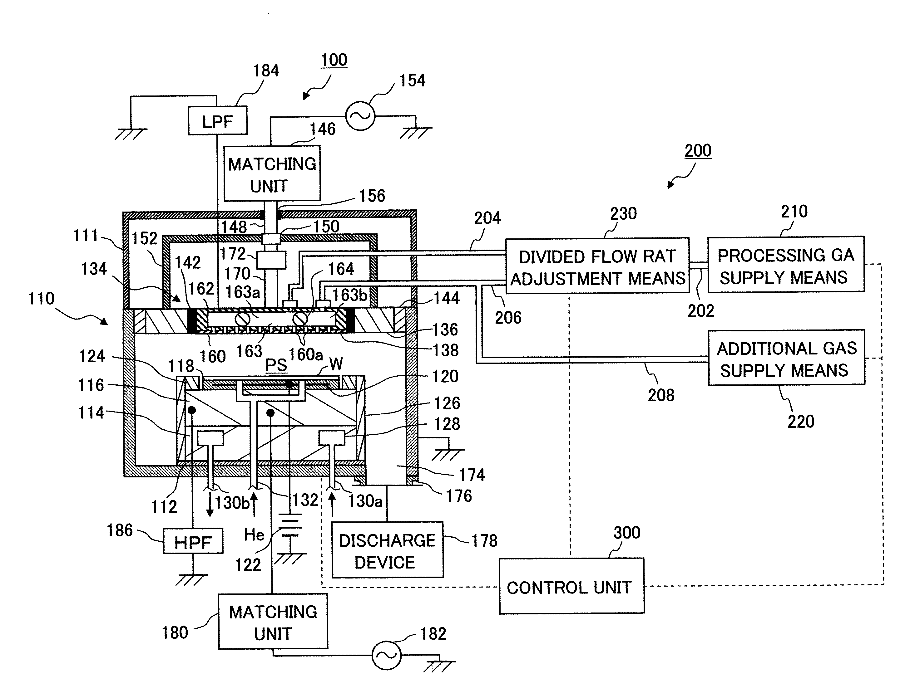
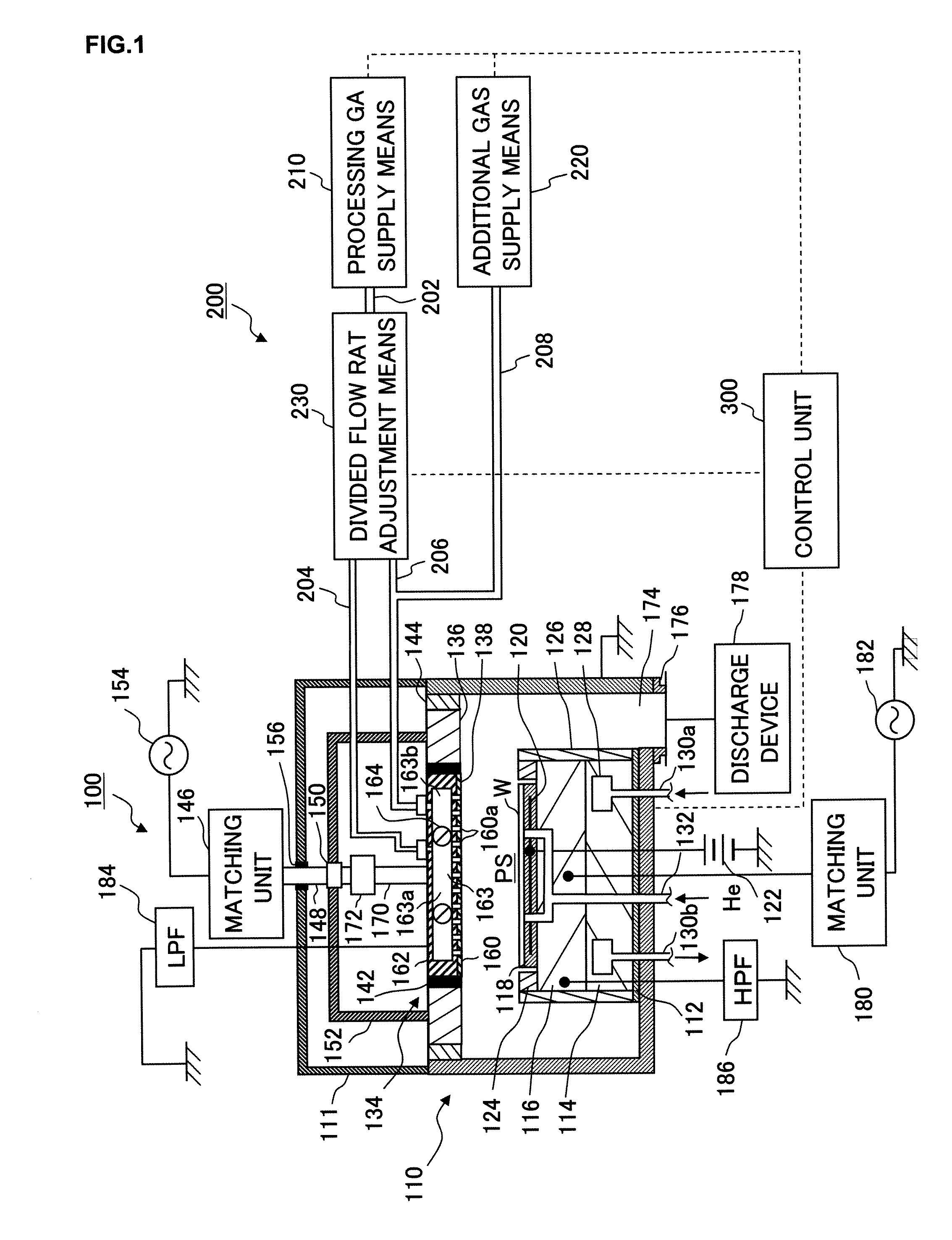
[0028]First, the substrate processing apparatus achieved in the embodiment of the present invention is explained in reference to a drawing. FIG. 1 is a sectional view schematically showing the structure adopted in the substrate processing apparatus in the embodiment. The substrate processing apparatus in the figure is a plain parallel plate-type plasma etching apparatus.

[0029]The substrate processing apparatus 100 includes a processing chamber 110 constituted with a substantially cylindrical processing container. The processing container, which may...


PUM

PropertyMeasurementUnit
frequencyaaaaaaaaaa
frequencyaaaaaaaaaa
frequencyaaaaaaaaaa

Abstract

Prior to wafer processing, pressure ratio control is executed on a divided flow rate adjustment means so as to adjust the flow rates of divided flows to achieve a target pressure ratio with regard to the pressures in the individual branch passages. As the processing gas from a processing gas supply means is diverted into first and second branch pipings under the pressure ratio control and the pressures in the branch passages then stabilize, the control on the divided flow rate adjustment means is switched to steady pressure control for adjusting the flow rates of the divided flows so as to hold the pressure in the first branch passage at the level achieved in the stable pressure condition. Only after the control is switched to the steady pressure control, an additional gas is delivered into the second branch passage via an additional gas supply means.

Description

CROSS-REFERENCE TO RELATED APPLICATIONS[0001]This document claims priority to Japanese Patent Application Number 2006-000241, filed on Jan. 4, 2006 and U.S. Provisional Application No. 60 / 773,676, filed on Feb. 16, 2006, the entire content of which are hereby incorporated by reference.FIELD OF THE INVENTION[0002]The present invention relates to a gas supply system that supplies gas into a processing chamber, a substrate processing apparatus and a gas supply method.BACKGROUND OF THE INVENTION[0003]In a substrate processing apparatus used in fields of application pertaining to the present invention, a specific type of processing such as film formation or etching is executed on a target substrate to undergo processing (hereafter simply referred to as a substrate), which may be a semiconductor wafer or a liquid crystal substrate, by using a specific gas supplied into a processing chamber.[0004]Such a substrate processing apparatus may be, for instance, a plasma processing apparatus. The...

Claims


Application Information

Patent Timeline
Patent Type & Authority Applications(United States)
IPC IPC(8): H01L21/306C23C16/00
CPCC23C16/45557C23C16/45561H01J37/32449H01J37/3244C23C16/5096Y10T137/0391
Inventor MIZUSAWA, KENETSU
Owner TOKYO ELECTRON LTD
Why Eureka
Try Eureka