
Motor vehicle capable of preventing malfunction and interrupting high-voltage system when accident occurs

a high-voltage system and motor vehicle technology, applied in vehicular safety arrangments, electric devices, process and machine control, etc., can solve the problems of high-voltage system interruption, insufficient output of impact sensor for activating air bags, and incurred costs for air bags to be repaired,

Active Publication Date: 2007-07-05
TOYOTA JIDOSHA KK
View PDF6 Cites 25 Cited by
  • Summary
  • Abstract
  • Description
  • Claims
  • Application Information

AI Technical Summary

Benefits of technology

The present invention is a motor vehicle with an air bag system that can detect and respond to impacts or malfunctions in a way that prevents damage or malfunction. This is achieved through a combination of sensors and control units that can detect and interrupt the high-voltage power supply system in response to impacts or other indicators of malfunction. This system can prevent accidents and malfunctions without requiring additional sensors and can also improve safety and reliability.

Problems solved by technology

However, there may be a case where the interruption of the high-voltage system based on an output of the air bag impact sensor for activating an air bag is insufficient.
In other words, the air bag impact sensor is configured to inflate an air bag only when a seat belt alone can cause injury to a passenger because the cost incurred to repair an air bag, for example, is large when it is once activated.
Instead, a high-voltage power supply system is required to be interrupted when a high-voltage electric system contained in an engine room on the front or rear side of the vehicle may be damaged due to an impact.
However, an additional impact sensor is needed, which causes an increase in cost and requires a mounting space therefor.
Accordingly, it is difficult to implement such a measure.

Method used


Image

  • Motor vehicle capable of preventing malfunction and interrupting high-voltage system when accident occurs
  • Motor vehicle capable of preventing malfunction and interrupting high-voltage system when accident occurs
  • Motor vehicle capable of preventing malfunction and interrupting high-voltage system when accident occurs

Examples


Embodiment Construction

[0026] An embodiment of the present invention will now be described in detail in reference to the drawings. The same or corresponding portions in the drawings are denoted by the same reference characters, and the description thereof will not be repeated.

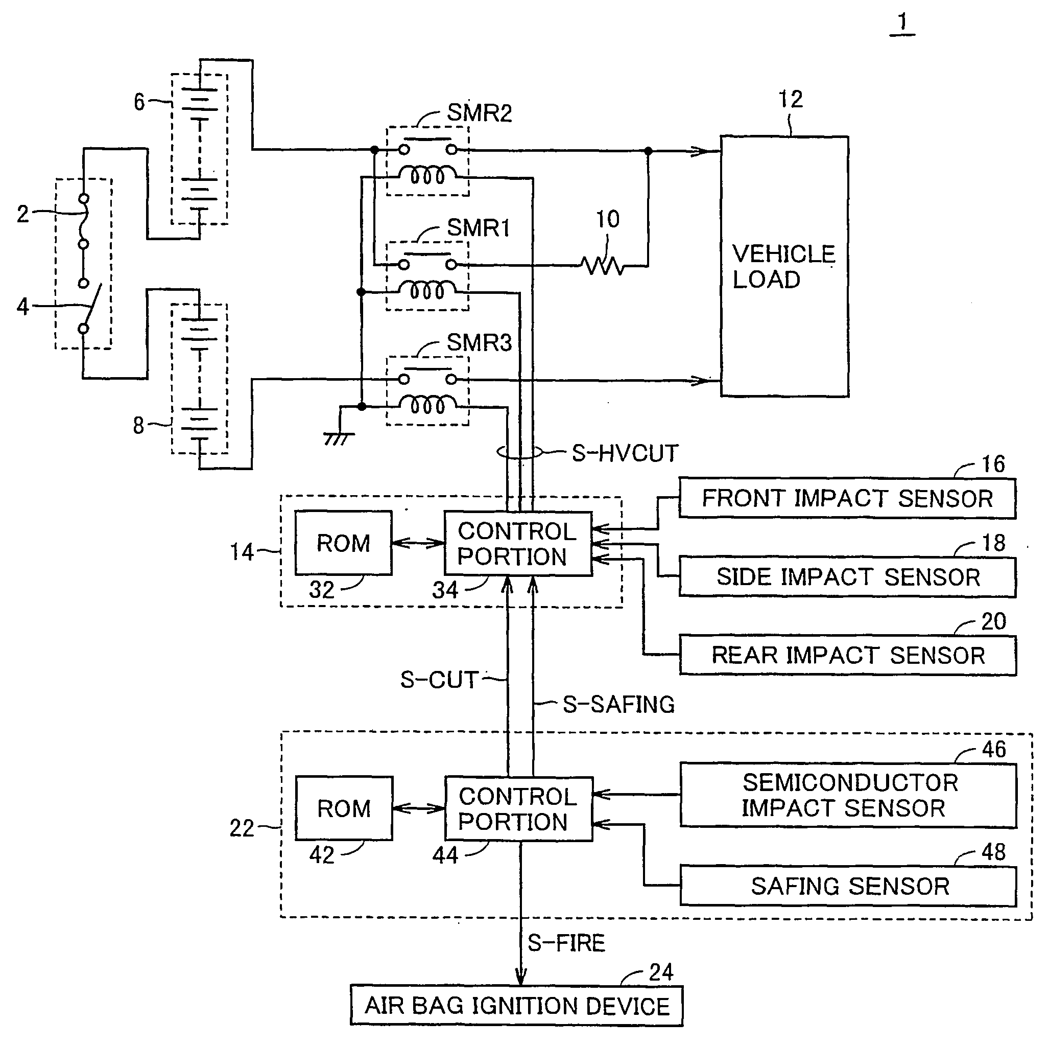
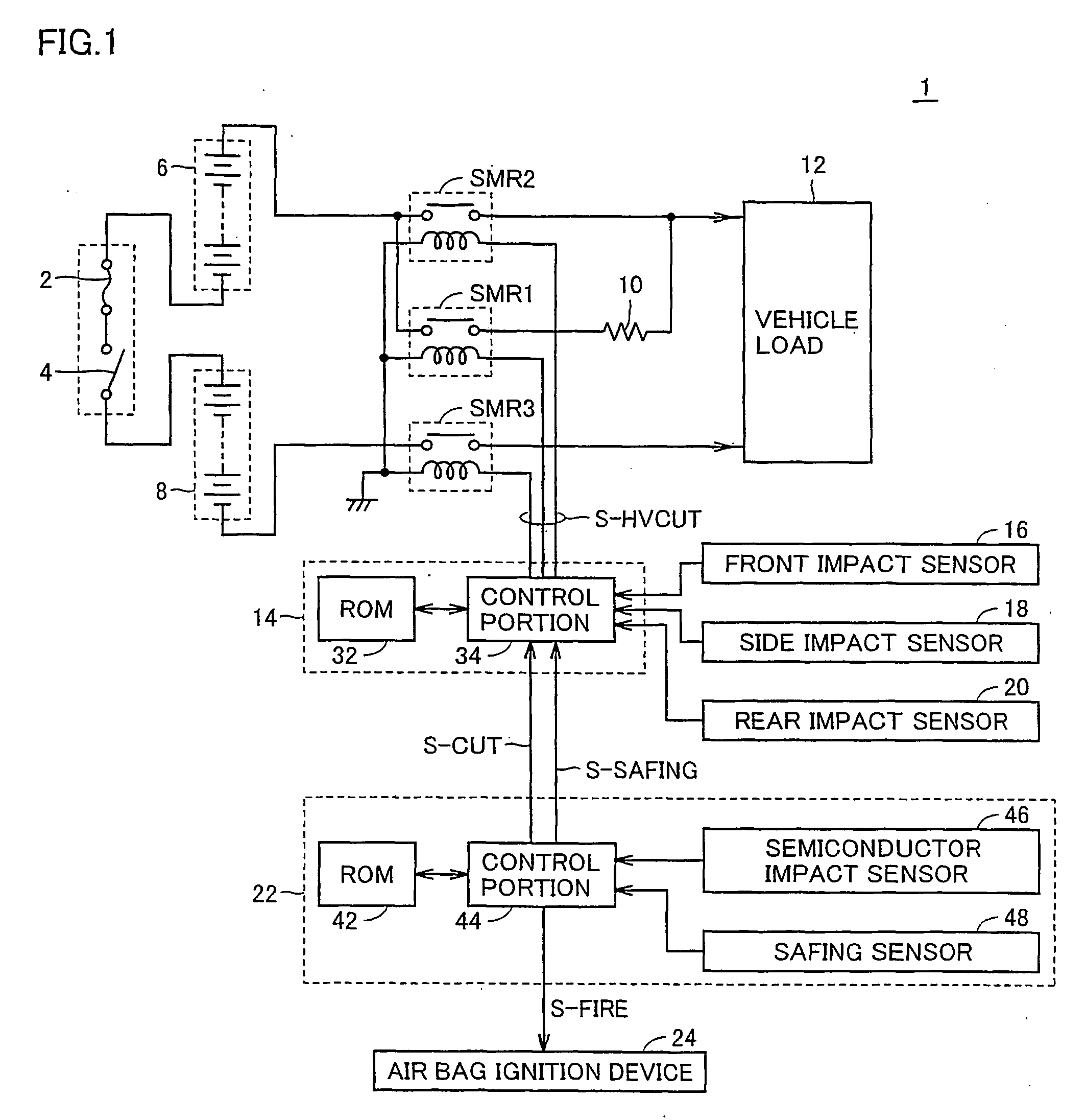
[0027]FIG. 1 is a circuit diagram for describing a high-voltage power supply system of a motor vehicle 1 according to the present invention.

[0028] Referring to FIG. 1, motor vehicle 1 includes battery modules 6 and 8 connected in series, a fuse 2 and a service plug 4 provided on a path connecting battery modules 6 and 8 in series, a vehicle load 12 for receiving power from battery modules 6 and 8, and system main relays SMR 1-SMR 3 for making a power supply path from battery modules 6 and 8 to vehicle load 12 conductive or interrupted.

[0029] Battery modules 6 and 8 have a voltage higher than a conventional 12V battery, and have a configuration in which 14 battery modules each having 7.2V, for example, are connected in series. Serv...


PUM


Abstract

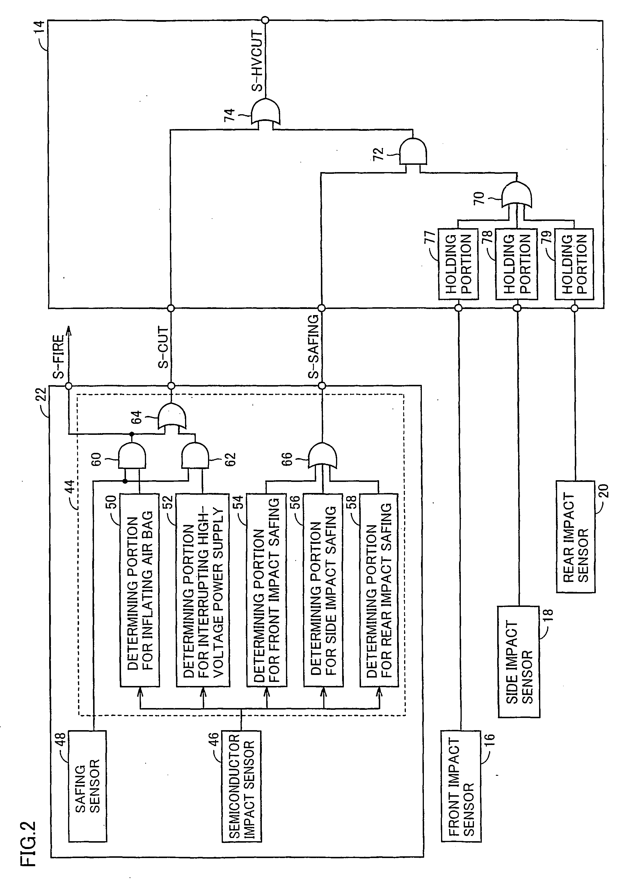
An output of a semiconductor impact sensor contained in an air bag ECU is used to make determination in light of a criterion for interrupting a high-voltage power supply, which is different from a criterion for inflating an air bag so that the semiconductor impact sensor forms a redundant system along with a conventional safing sensor to prevent malfunction. Furthermore, an output of the semiconductor impact sensor contained in the air bag ECU is used to make determination for safing and output a safing signal thereby, so that a redundant system can be formed for a front impact sensor, a side impact sensor, and a rear impact sensor. Accordingly, malfunction can be prevented when tampering such as a strike with a hammer occurs.

Description

TECHNICAL FIELD [0001] The present invention relates to a motor vehicle, and, more particularly, to a motor vehicle having a high-voltage electric system. BACKGROUND ART [0002] In recent years, there have been developed an electric vehicle, a hybrid vehicle, and a fuel-cell vehicle, whose motor is driven by a power supply of much higher voltage to propel the vehicle when compared to a battery of approximately 12 volt mounted on a conventional motor vehicle. For each of these vehicles having a high-voltage electric system, it is necessary to quickly interrupt the high-voltage power supply system thereof to prevent vehicle fire and electric shock accident in the case of impact. When the high-voltage system is interrupted, however, it is impossible to move the vehicle, and thus malfunction should be avoided. [0003] For example, Japanese Patent Laying-Open No. 2002-354602 discloses a technique of using an impact sensor provided for inflating an air bag to interrupt a high-voltage system...

Claims


Application Information

Patent Timeline
Patent Type & Authority Applications(United States)
IPC IPC(8): B60L1/00B60R21/01
CPCB60K28/14B60L3/04B60L3/12B60L11/1864Y02T10/7061B60L2240/549B60R21/017Y02T10/7005B60L2240/547B60L58/21Y02T10/70B60R16/02B60R21/01B60L50/50
Inventor UCHIDA, KENJI
Owner TOYOTA JIDOSHA KK
Learn More