
Display apparatus and power control method thereof

a technology of display apparatus and power control method, which is applied in the direction of instruments, television systems, static indicating devices, etc., can solve the problems of increasing the standby power consumption of the whole tmds receiver, and achieve the effect of reducing the loss of clock signal and reducing standby power consumption

Inactive Publication Date: 2007-07-05
SAMSUNG ELECTRONICS CO LTD
View PDF5 Cites 37 Cited by
  • Summary
  • Abstract
  • Description
  • Claims
  • Application Information

AI Technical Summary

Benefits of technology

[0008]Accordingly, it is an aspect of the present invention to provide a display apparatus, which is capable of determining the presence of a TMDS signal through a clock signal detecting part before the TMDS signal is input to a TMDS receiving part, thereby reducing standby power consumption by stopping supply of power to the TMDS receiving part in a standby mode, and reducing loss of the clock signal, which may occur due to branch from a clock line, when the TMDS signal is detected, and a power control method thereof.
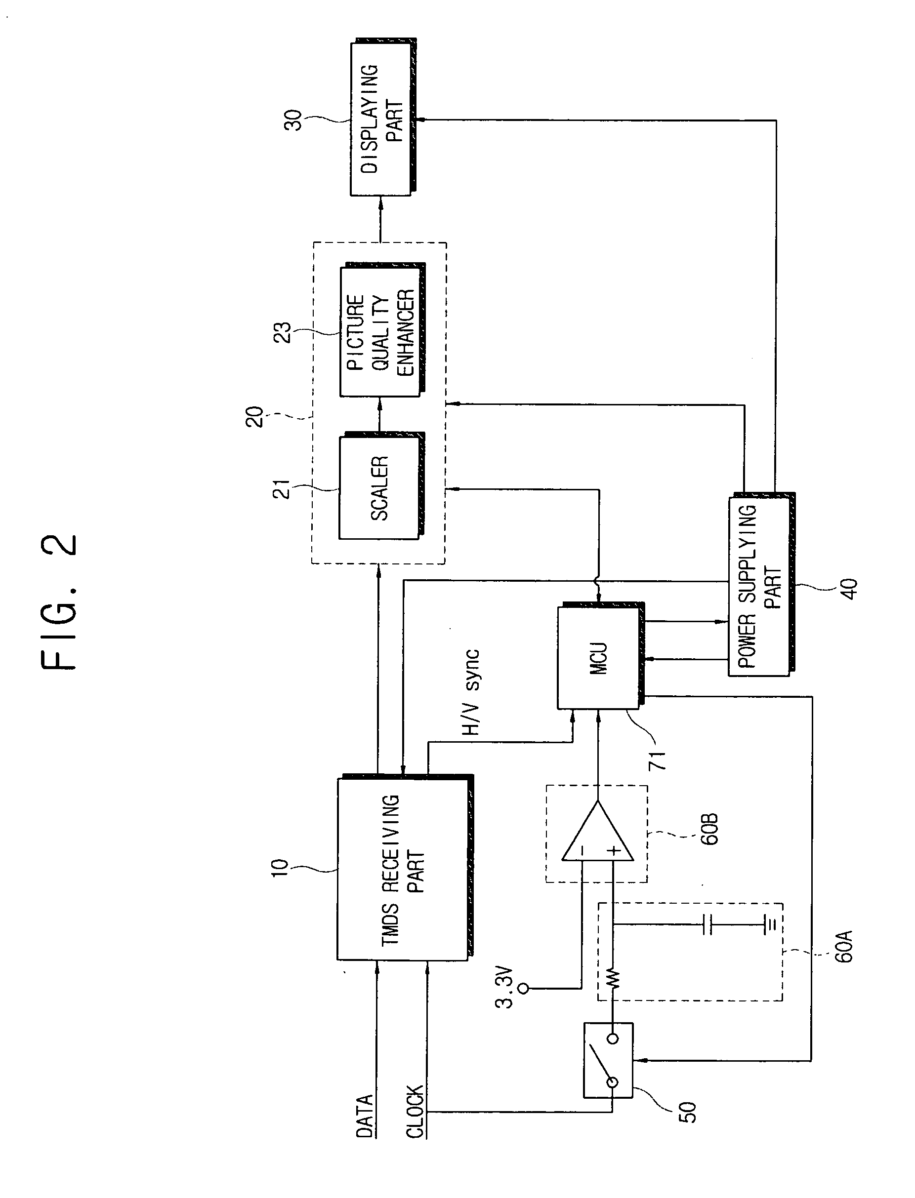
[0017]According to an exemplary embodiment of the present invention, the signal processing part comprises a scaler which scales the TMDS signal decoded by the TMDS receiving part to conform to the output format of the displaying part, and a picture quality enhancer which enhances a quality of the scaled TMDS signal.
[0022]According to an exemplary embodiment of the present invention, the signal processing part comprises a scaler which scales the TMDS signal decoded by the TMDS receiving part to conform to the output format of the displaying part, and a picture quality enhancer which enhances a quality of the scaled TMDS signal.

Problems solved by technology

However, since such a related art display apparatus may or may not enter the power-saving mode depending on whether or not the synchronization signal from the TMDS receiver is detected, standby power has to be supplied to the TMDS receiver in order to detect the synchronization signal in the power-saving mode.
In this case, the TMDS receiver consumes a current of about 700 mA which increases the standby power consumption of the whole TMDS receiver.

Method used


Image

  • Display apparatus and power control method thereof
  • Display apparatus and power control method thereof
  • Display apparatus and power control method thereof

Examples


Embodiment Construction

[0033]Reference will now be made in detail to exemplary embodiments of the present invention, examples of which are illustrated in the accompanying drawings.

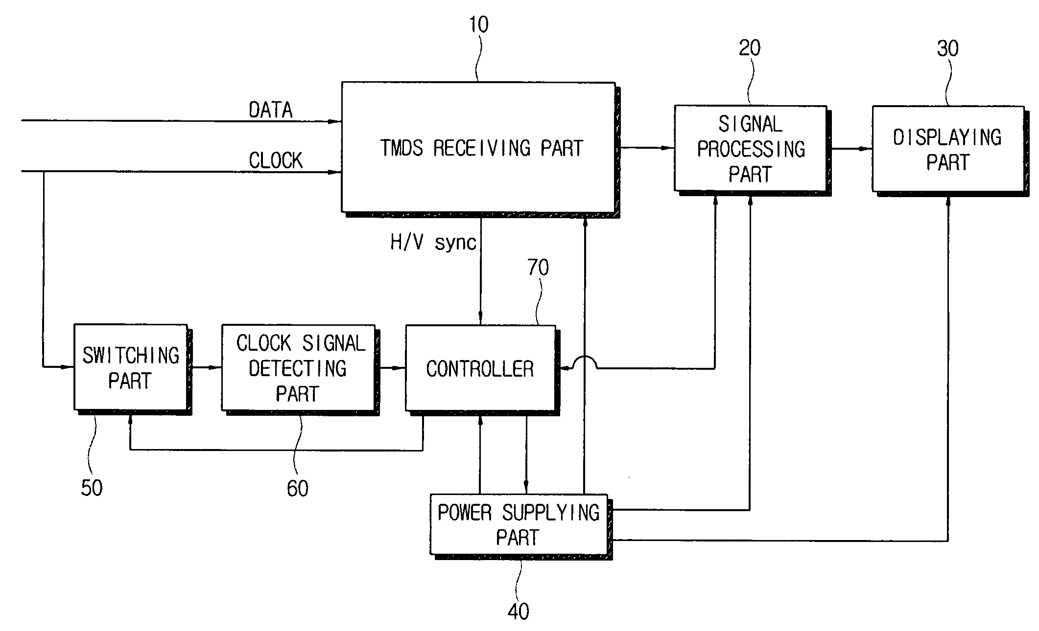
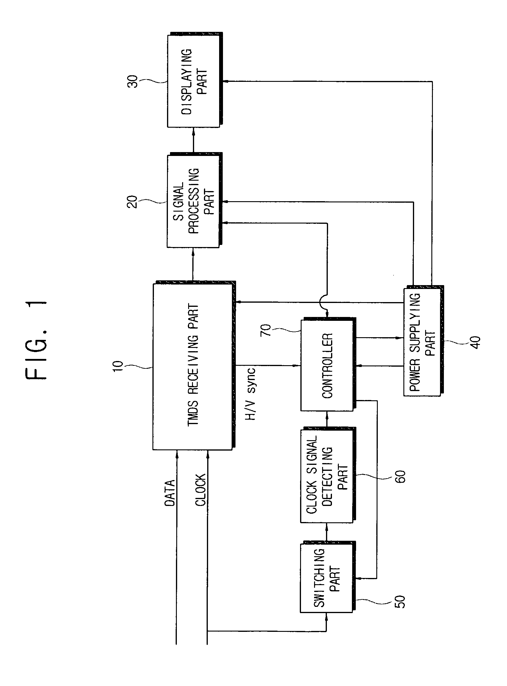
[0034]FIG. 1 is a control block diagram of a display apparatus according to an exemplary embodiment of the present invention.

[0035]Referring to FIG. 1, a display apparatus according to an exemplary embodiment of the present invention comprises a TMDS receiving part 10, a signal processing part 20, a displaying part 30, a power supplying part 40, a switching part 50, a clock signal detecting part 60 and a controller 70.

[0036]The TMDS receiving part 10 decodes a TMDS signal received from an external signal source to conform to the process standard of the signal processing part 20. The TMDS receiving part 10 may comprise a decoder. The TMDS signal, which is a digital signal, may have a DVI or HDMI format. Specifically, when the external signal source transmits high-speed serial data into which parallel data are modulated, the TMDS ...


PUM


Abstract

A display apparatus and a power control method thereof are provided. The display apparatus includes a power supplying part; a Transition Minimized Differential Signaling (TMDS) receiving part which decodes a TMDS signal input from an external signal source; a controller which controls the power supplying part to supply driving power to the TMDS receiving part when a clock signal of the TMDS signal is received. The power control method includes cutting off driving power to a Transition Minimized Differential Signaling (TMDS) receiving part when the display apparatus enters a power-saving mode; determining whether a clock signal is detected in a TMDS signal; and supplying driving power to the TMDS receiving part if it is determined that the clock signal is detected.

Description

CROSS-REFERENCE TO RELATED APPLICATIONS[0001]This application claims priority from Korean Patent Application No. 10-2006-0001404, filed on Jan. 5, 2006, the disclosure of which is incorporated herein by reference in its entirety.BACKGROUND OF THE INVENTION[0002]1. Field of the Invention[0003]Apparatuses and methods consistent with the present invention relate to a display apparatus having a Transition Minimized Differential Signaling (TMDS) receiver that receives and decodes a signal of a TMDS format, which is a digital signal, and a power control method thereof.[0004]2. Description of the Related Art[0005]A TMDS signal, which is a kind of digital video signal, is input from a signal source, such as a computer or the like, to a TMDS receiver of a display apparatus through a Digital Video Interface (DVI) or a High Definition Multimedia Interface (HDMI). The TMDS receiver decodes the received TMDS signal into a signal of a format which can be processed by the display apparatus.[0006]A...

Claims


Application Information

Patent Timeline
IPC IPC(8): G09G5/00
CPCH04N5/63G09G5/003G09G5/006G09G2330/021G09G2370/12G09G2370/22A47G25/12A01G9/045
Inventor KOH, HYUNG-IL
Owner SAMSUNG ELECTRONICS CO LTD
Learn More