Digital camera

a digital camera and mirror technology, applied in the field of digital cameras, can solve the problems of insufficient improvement of the operation of the movable mirror switching and difficulty for users to use, and achieve the effect of improving the operation of the mirror switching

Active Publication Date: 2007-07-05
PANASONIC INTELLECTUAL PROPERTY MANAGEMENT CO LTD
View PDF53 Cites 83 Cited by
  • Summary
  • Abstract
  • Description
  • Claims
  • Application Information

AI Technical Summary

Benefits of technology

[0008] The object of the present invention is to provide a digital camera with the operability thereof enhanced, which includes a movable mirror and is capable of displaying a subject image in a live view through an electronic viewfinder.
[0011] According to the present invention, in a digital camera that includes a movable mirror and is capable of displaying a live view through an electronic viewfinder, the operability thereof can be enhanced.

Problems solved by technology

However, in the digital single-lens reflex camera disclosed by Patent Document 1, the operability involved in switching of the movable mirror is not improved sufficiently.
Therefore, even if the live view mode is set to be executable, it is difficult for a user to use it, and consequently, the user captures an image while observing it with the optical viewfinder.

Method used


Image

  • Digital camera
  • Digital camera
  • Digital camera

Examples


embodiment 1

(1-1 Configuration of Digital Camera).

[0104] [1-1-1 Outline of Entire Configuration]

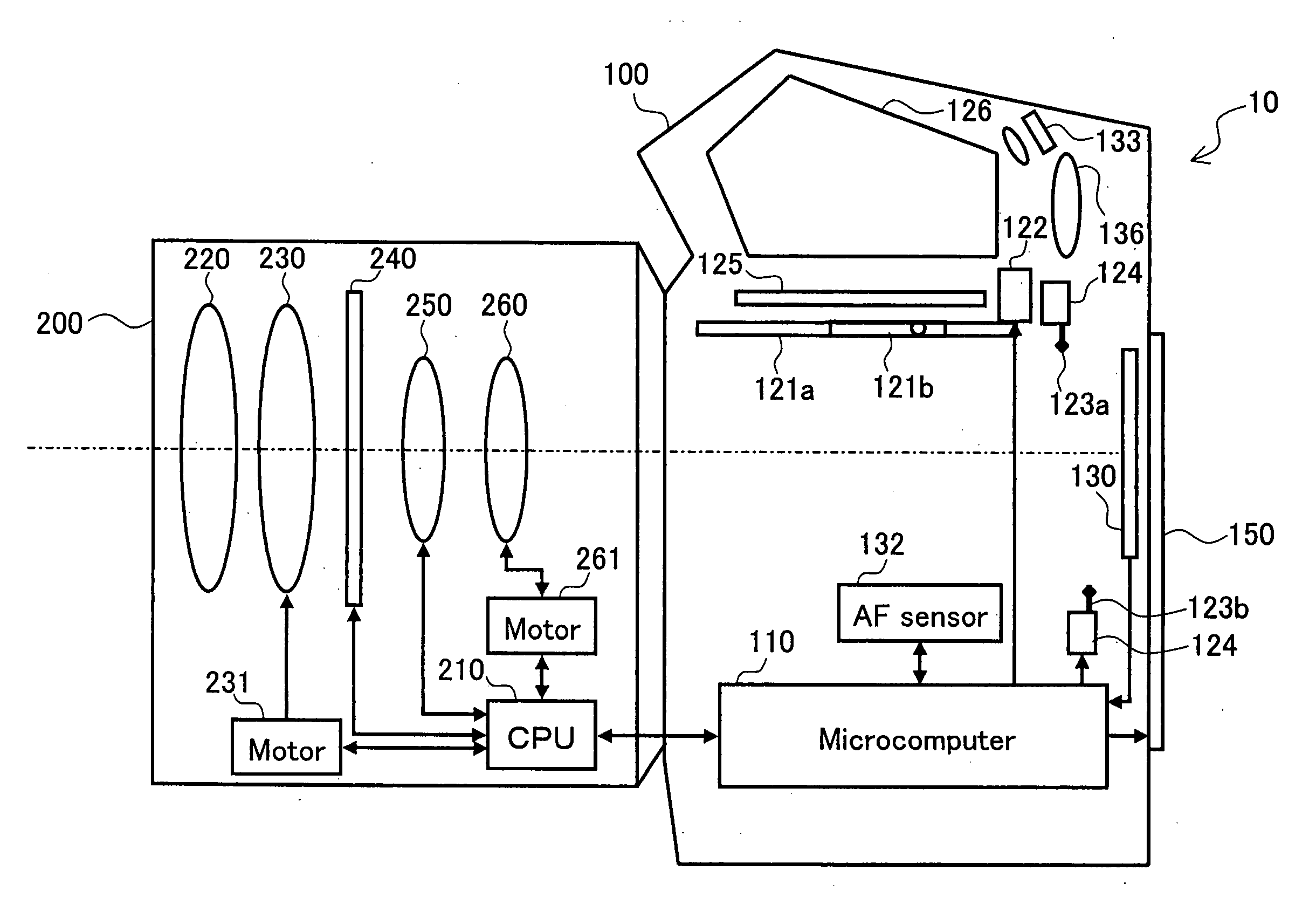
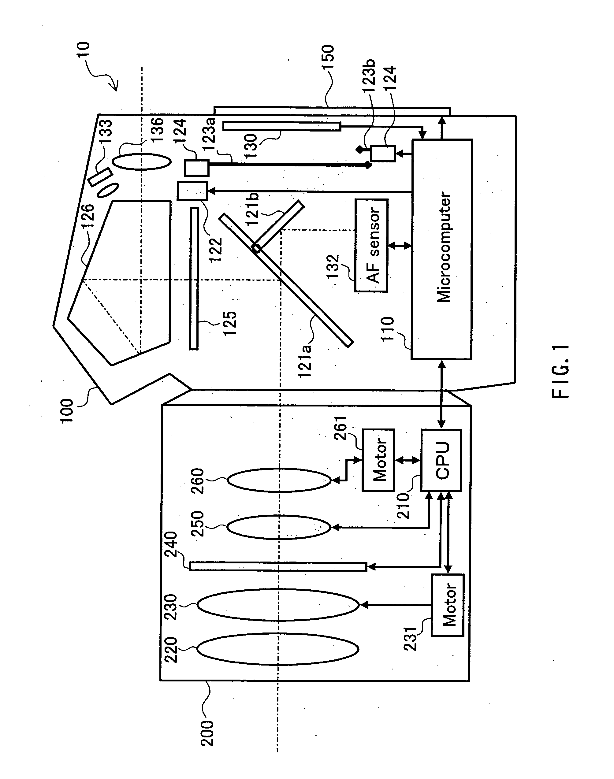
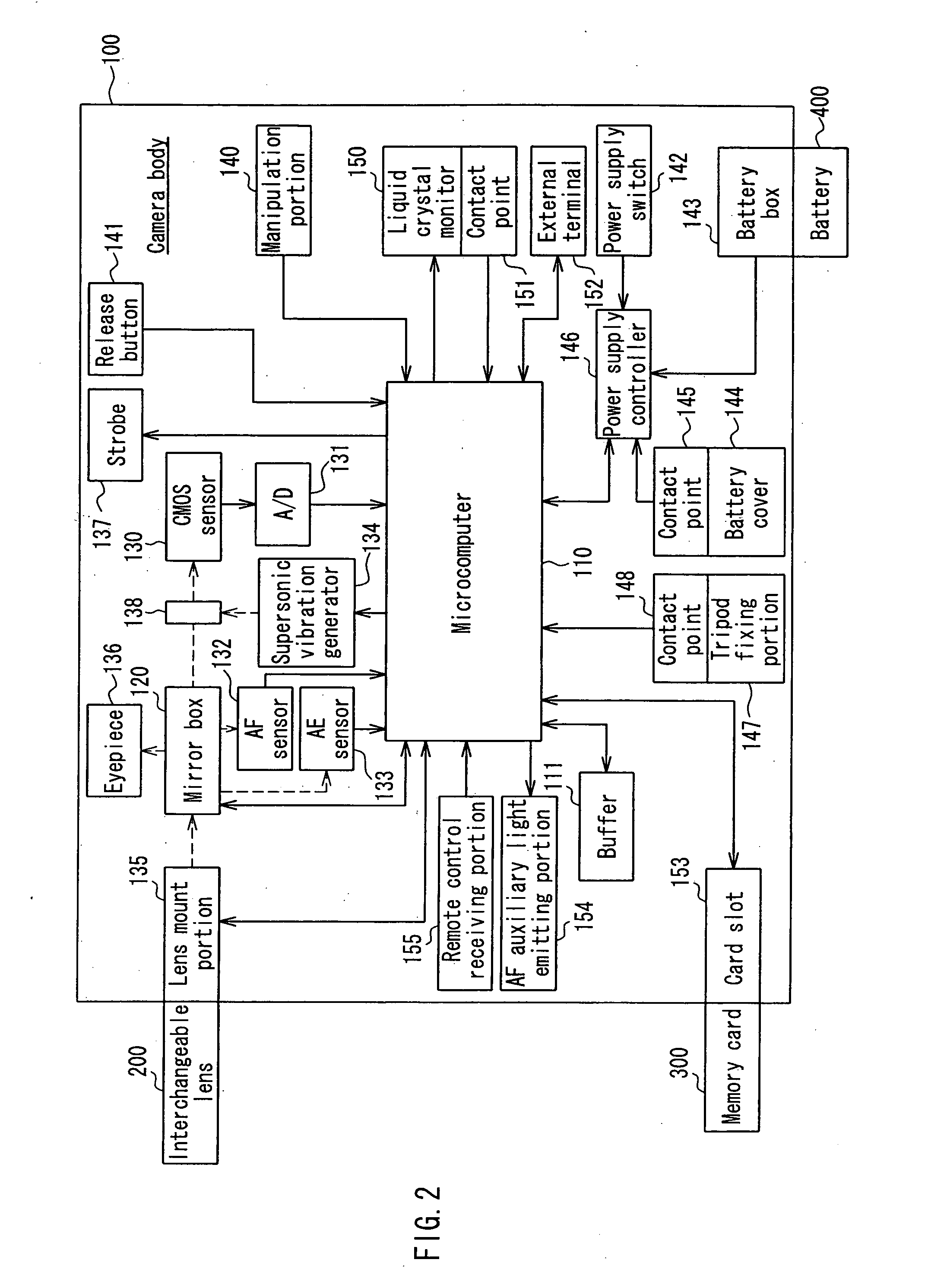
[0105]FIG. 1 is a schematic view illustrating a configuration of a camera 10. The camera 10 is composed of a camera body 100 and an interchangeable lens 200 attachable / detachable with respect to the camera body 100.

[0106] The camera body 100 captures a subject image condensed by an optical system included in the interchangeable lens 200, and records it as image data. The camera body 100 includes a mirror box 120. The mirror box 120 switches an optical path of an optical signal from the optical system included in the interchangeable lens 200 so as to allow the subject image to be incident selectively upon either a CMOS sensor 130 (complementary metal-oxide semiconductor) or an eyepiece 136. The mirror box 120 includes movable mirrors 121a, 121b, a mirror driving portion 122, a shutter 123, a shutter driving portion 124, a focusing glass 125, and a prism 126.

[0107] The movable mirror 121a is placed...

embodiment 2

[0343] The camera 10 in Embodiment 1 switches an OVF mode to a live view mode by a manual manipulation of the viewfinder switch 140e. However, it is inconvenient if the OVF mode cannot be switched to the live view mode without a manual manipulation at all times. Particularly, in the case where it is highly necessary to switch to the live view mode, if the OVF mode can be switched to the live view mode automatically, the operability of the user can be enhanced. In Embodiment 2, a camera capable of switching to the live view mode automatically in accordance with various events is realized.

[0344] The configuration of the camera 10 in Embodiment 2 is similar to that of the camera 10 in Embodiment 1, so that the description thereof will be omitted.

[0345] [2-1 Operation of Shifting to Live View Mode by Diaphragm Adjustment]

[0346] In the above-mentioned Embodiment 1, in order to observe a depth of field when an image for recording is captured in a live view mode, the stop-down button 140...

embodiment 3

[0406] In the camera 10 according to the above-mentioned Embodiment 1, by manually manipulating the viewfinder switch 140e, the live view mode is switched to the OVF mode. However, it is inconvenient if the live view mode cannot be switched without manual manipulation at all times. Particularly, in the case where it is highly necessary to come out of the live view mode, if the live view mode can be switched automatically, the operability of the user can be enhanced. The camera in Embodiment 3 is configured so as to come out of the live view mode automatically in accordance with various events.

[0407] The configuration of the camera 10 according to Embodiment 3 is similar to that of the camera 10 according to Embodiment 1, so that the description thereof will be omitted.

[0408] [3-1 Operation of Canceling Live View Mode by Operation of Menu Button]

[0409] In the above-mentioned Embodiment 1, when the menu button 140a is manipulated in the live view mode, a menu screen is overlapped wi...


PUM


Abstract

A digital camera of the present invention includes a microcomputer 110 having a live view mode controlling so that image data generated by a CMOS sensor 130 or image data obtained by subjecting the image data generated by the CMOS sensor 130 to predetermined processing is displayed on a liquid crystal monitor 150 as a moving image in real time, and the microcomputer 110 controls so that movable mirrors 121a and 121b to enter an optical path of an image pickup optical system after the amount of light from a subject is obtained based on the image data generated by the CMOS sensor 130, a strobe 137 emits light, and measurement results of an AE sensor 133 are obtained. Due to this configuration, in a digital camera that includes a movable mirror and is capable of displaying a subject image in a live view through an electronic viewfinder, the operability thereof can be enhanced.

Description

BACKGROUND OF THE INVENTION [0001] 1. Field of the Invention [0002] The present invention relates to a digital camera. In particular, the present invention relates to a digital camera having a movable mirror, which enables a subject image to be observed through an electronic viewfinder. [0003] 2. Description of Related Art [0004] A digital single-lens reflex camera has an electronic viewfinder and an optical viewfinder, so that a subject image formed by an image pickup optical system is switched with a movable mirror, and can be observed through the optical viewfinder. Because of this, displacement does not occur between a subject image in a recording image and a subject image displayed with the optical viewfinder, whereby an image pickup manipulation can be performed satisfactorily. [0005] However, the digital single-lens reflex camera needs to switch the movable mirror in accordance with an operation state. This requires a user's manual manipulation, and a time therefor needs to b...

Claims


Application Information

Patent Timeline
Patent Type & Authority Applications(United States)
IPC IPC(8): G02B13/16G02B7/28G02B7/36H04N5/232G03B13/36H04N101/00
CPCG03B19/12H04N5/2254H04N5/23245H04N5/23203H04N5/238G03B19/00H04N5/23212H04N5/23293H04N23/672H04N23/673H04N23/651H04N23/667H04N23/635H04N23/75H04N23/00H04N23/66
Inventor UEDAHONJO, KENICHIYUMIKI, NAOTOMAKABE, TOSHIOMAEDA, KENJIMOKUNAKA, KAORUISHIMARU, KAZUHIKO
Owner PANASONIC INTELLECTUAL PROPERTY MANAGEMENT CO LTD
Why Eureka
Try Eureka