Two-dimensional image display device

a display device and two-dimensional technology, applied in the field of two-dimensional image display devices, can solve the problems of deteriorating luminance of light from the light source on the screen, reducing the beam power of the light source, and affecting the quality of the image, so as to improve the quietness and durability, and reduce the cost

Inactive Publication Date: 2007-07-05
PANASONIC CORP
View PDF6 Cites 50 Cited by
  • Summary
  • Abstract
  • Description
  • Claims
  • Application Information

AI Technical Summary

Benefits of technology

[0047] In the two-dimensional image display device according to the present invention, since the optical system for removing speckle noise is constituted by a polarization state modulator and a birefringent diffusion plate, a driving system for vibrating or rotating the screen or the diffusion plate is dispensed with, whereby miniaturization and cost reduction can be achieved, and further, quietness and durability can be improved.
[0048] Furthermore, since the two-dimensional image display device of the present invention employs the high-speed polarization state modulator, the speckle patterns can be varied at high speed. Therefore, the two-dimensional image display device of the present invention is applicable to a two-dimensional scanning type high-resolution image display device, and it is possible to project a vivid and high-definition image which has no minute and uneven noises, onto a screen.

Problems solved by technology

In this case, however, the beam power of the light source decreases due to scattering and absorption of light by the liquid crystal, and thereby the luminance of the light from the light source on the screen is deteriorated.
In this laser display, however, there occurs a problem of so-called speckle noises in which bright-dot and dark-dot patterns are distributed at random, which are caused by that the high-coherence laser sources are used as light sources.

Method used


Image

  • Two-dimensional image display device
  • Two-dimensional image display device
  • Two-dimensional image display device

Examples


embodiment 1

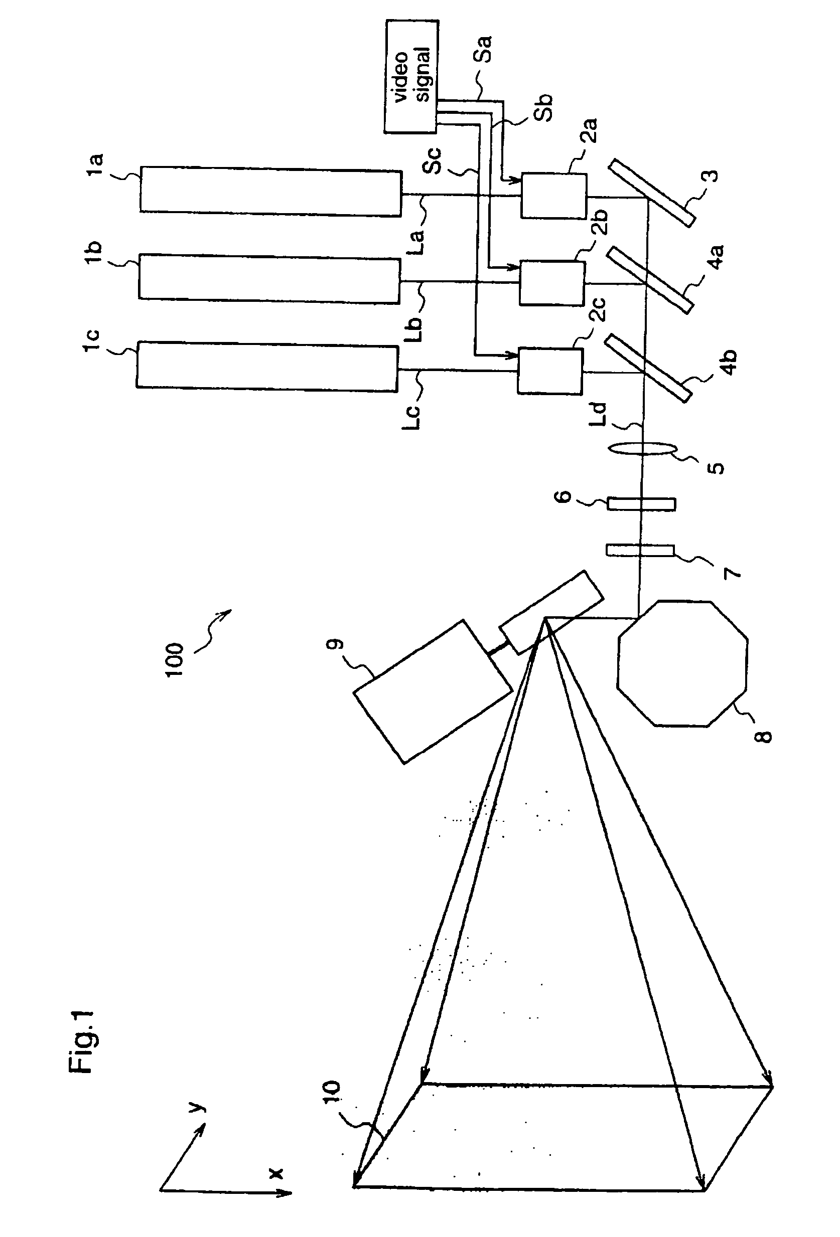
[0085]FIG. 1 is a diagram illustrating a schematic construction of a two-dimensional image display device according to a first embodiment of the present invention.

[0086] The two-dimensional image display device 100 shown in figure 1 includes laser sources 1a˜1c corresponding to three colors of R, G, B, and light modulators 2a˜2c for intensity-modulating laser lights La˜Lc emitted from the laser sources 1a˜1c according to primary color signals Sa˜Sc of an input video signal. The laser sources 1a, 1b, and 1c may be vapor lasers such as He—Ne lasers, He—Cd lasers, or Ar lasers, semiconductor laser such as AlGaInP or GaN system lasers, or SHG (Second Harmonic Generation) lasers having an output of a solid laser as a base wave.

[0087] Further, the laser display 100 includes a mirror 3 for reflecting the laser light La modulated by the optical modulator 2a, a dichroic mirror 4a for multiplexing the laser light La reflected at the mirror 3 and the laser light Lb modulated by the light mod...

embodiment 2

[0119] FIGS. 5(a) and 5(b) are diagrams for explaining a two-dimensional image display device according to a second embodiment of the present invention. FIG. 5(a) is a plan view illustrating a birefringent diffusion plate 7c as a constituent of the two-dimensional image display device. FIG. 5(b) illustrates a cross-sectional structure of the birefringent diffusion plate 7c, and schematically illustrates phase distributions of illumination light incident on the birefringent diffusion plate 7c and illumination light emitted from the birefringent diffusion plate 7c.

[0120] The two-dimensional image display device according to the second embodiment uses the birefringent diffusion plate 7c in which the thickness of a substrate comprising a material having birefringence is spatially varied at random, instead of the birefringent diffusion plate 7 of the two-dimensional image display device 100 of the first embodiment. Accordingly, other constituents of this second embodiment are identical ...

embodiment 3

[0133]FIG. 7 is a diagram for explaining a two-dimensional image display device according to a third embodiment of the present invention, schematically illustrating a speckle noise removal optical system in the two-dimensional image display device.

[0134] In the two-dimensional image display device according to the third embodiment, the polarization state modulator 6 and the birefringent diffusion plate 7c which constitute the speckle noise removal optical system of the second embodiment are integrated. Other constituents of the third embodiment are identical to those of the second embodiment.

[0135] The speckle noise removal optical system of the two-dimensional image display device according to the third embodiment is obtained by integrating, on a single LiNbO3 crystal, a polarization state modulator 6e for modulating the polarization state of laser light Ld, and a birefringent diffusion plate 7e for spatially varying the phase of the laser light whose polarization state is modula...


PUM

PropertyMeasurementUnit
modulation frequencyaaaaaaaaaa
cell widthaaaaaaaaaa

Abstract

In a two-dimensional image display device, speckle noise is reduced by a simple construction. A two-dimensional image display device for displaying an image by projecting coherent light onto a projection plane is provided with at least one coherent light source (1a), (1b), (1c) for outputting coherent light, a polarization state modulator 6 for modulating at least one of a polarization state and a phase of the coherent light emitted from the coherent light source, and a birefringent diffusion plate 7 for spatially varying the phase of the coherent light emitted from the polarization state modulator, wherein the polarization states of light spots in the respective pixels of the image displayed on the projection plane are spatially and temporally varied, thereby forming various speckle patterns.

Description

TECHNICAL FIELD [0001] The present invention relates to a two-dimensional image display device and, more particularly, to reduction in speckle noise in a two-dimensional scanning type image display device using a coherent light source as a light source. BACKGROUND ART [0002]FIG. 9 is a diagram illustrating a schematic structure of a conventional laser display. [0003] The laser display 900 includes laser sources 901a˜901c corresponding to three colors of R, G, B, and light modulators 905a˜905c for intensity-modulating laser lights La˜Lc emitted from the laser sources 901a˜901c according to primary color signals Sa˜Sc of an input video signal. Further, the laser display 900 includes a mirror 903 for reflecting the laser light La modulated by the optical modulator 906a, a dichroic mirror 902a for multiplexing the laser light La reflected at the mirror 903 and the laser light Lb modulated by the light modulator 906b, a dichroic mirror 902b for multiplexing the laser light La from the di...

Claims


Application Information

Patent Timeline
Patent Type & Authority Applications(United States)
IPC IPC(8): G03B21/14G02F1/03G02F1/07G02F1/01G03B21/00
CPCG02F1/0136G03B21/14G03B21/00G03B21/006G03B21/2073G03B21/208
Inventor MORIKAWA, AKIHIROKASAZUMI, KEN'ICHIMIZUUCHI, KIMINORI
Owner PANASONIC CORP
Why Eureka
Try Eureka