
Battery assembly employed with separator of sealed top portion and secondary battery comprising the same

Active Publication Date: 2007-07-05
LG ENERGY SOLUTION LTD
View PDF0 Cites 31 Cited by
  • Summary
  • Abstract
  • Description
  • Claims
  • Application Information

AI Technical Summary

Benefits of technology

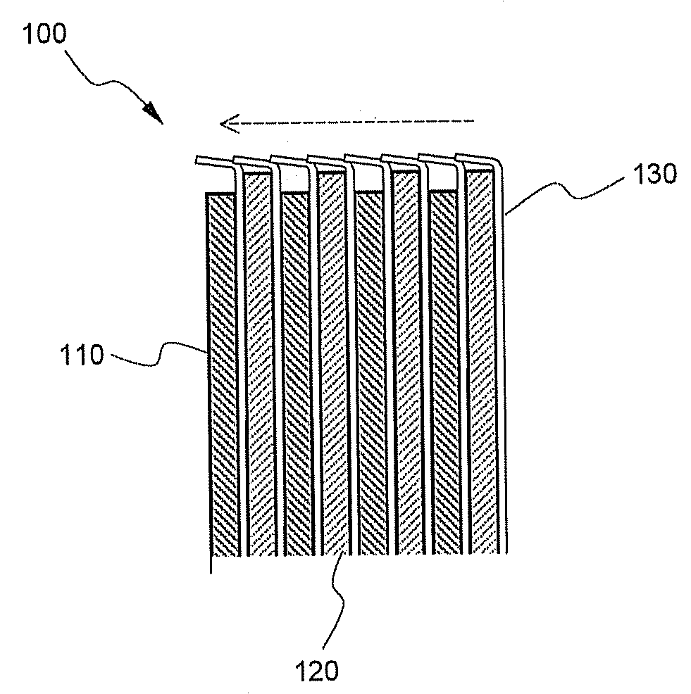
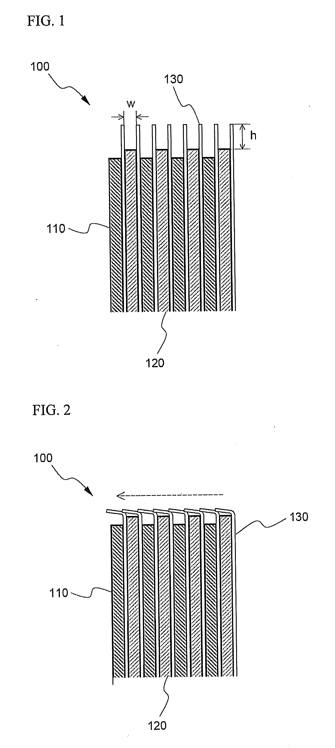
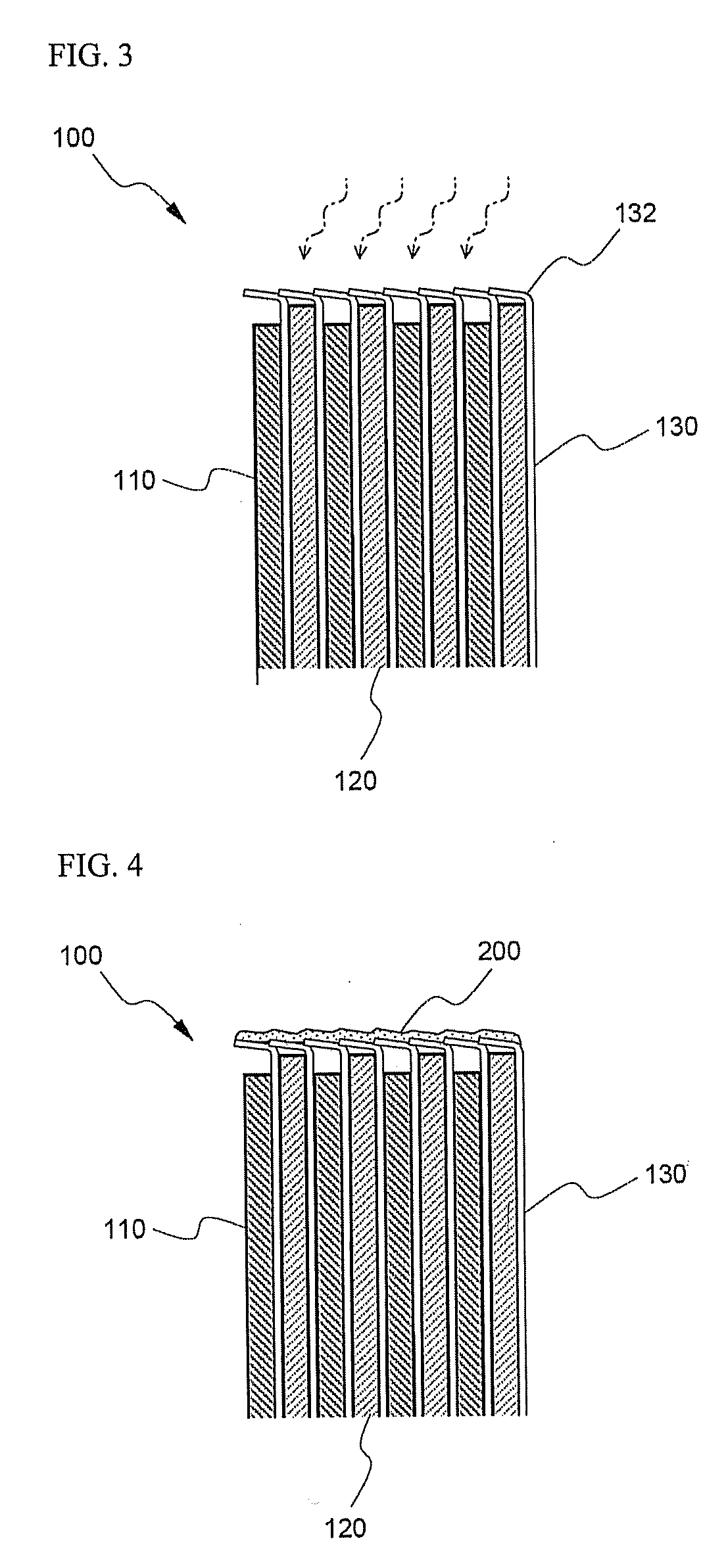
[0011]As a result of a variety of extensive and intensive studies and experiments to solve the problems as described above, the inventors of the present invention have found that, when an electrode assembly is constructed such that separators, which are disposed respectively between anodes and cathodes, protrude higher than the anodes and the cathodes, the protruding separators are bent in one direction, the separators are heat-treated such that the bent state of the separators is fixed, and an insulative coating layer is formed at the upper ends of the separators, thermal damage to the electrodes is minimized, and the occurrence of short circuits due to introduction of foreign matter into the electrode assembly is prevented. The present invention has been completed based on these findings.
[0025]The secondary battery according to the present invention does not need an additional insulating member mounted to the upper end of the electrode assembly, which is required in general secondary batteries. Consequently, the manufacturing process of the secondary battery having this structure is simplified, and the manufacturing costs of the secondary battery having this structure are reduced.

Problems solved by technology

When the protruding length of the separators is too small, it is not possible for the separators to completely cover the upper ends of the electrodes with the result that it is difficult to accomplish the sealability although the separators are bent, heat-treated such that the bent state of the separators is fixed, and the insulative coating layer is formed as described above.
When the protruding length of the separators is too large, on the other hand, the overlapping regions are increased with the result that the size of the electrode assembly is increased.

Method used


Image

  • Battery assembly employed with separator of sealed top portion and secondary battery comprising the same
  • Battery assembly employed with separator of sealed top portion and secondary battery comprising the same
  • Battery assembly employed with separator of sealed top portion and secondary battery comprising the same

Examples


example 1

1-1. Manufacture of Cathodes

[0036]A mixture including 96 weight percent of LiCoC2, 1.5 weight percent of Super-P (a conducting agent), and 2.5 weight percent of PVDF (a coupling agent), as a cathode active material, was added to NMP (N-methyl-2-pyrrolidone), as a solvent, so as to manufacture cathode mixture slurry. Subsequently, the cathode mixture slurry was applied to aluminum current collectors, which were dried and pressed. In this way, cathodes were manufactured.

1-2. Manufacture of Anodes

[0037]A mixture including 95.5 weight percent of artificial graphite, 1.5 weight percent of Super-P (a conducting agent), and 3 weight percent of PVDF (a coupling agent), as an anode active material, was added to NMP, as a solvent, so as to manufacture anode mixture slurry. Subsequently, the anode mixture slurry was applied to copper current collectors, which were dried and pressed. In this way, anodes were manufactured.

1-3. Manufacture of Electrolytic Solution

[0038]An electrolytic solution wa...

experimental example 1

[0042]The batteries manufactured as described in Example 1 and Comparative example 1 were dropped from a height of 4 feet with the top, the bottom, and the side thereof down 15 times each so as to measure whether foreign matter was introduced into the electrode assemblies. The measurement results are indicated in Table 1.

TABLE 1Size of ForeignQuantity ofCode nameTypematterSampleResultsComparativeAChip10Introduction ofexampleForeign matterBPowder10Introduction ofForeign matterExampleAChip10Nonintroduction ofForeign matterBPowder10Nonintroduction ofForeign matter* Chip size: ≧ 500 μm, Powder size: 44 to 150 μm

[0043]It can be seen from Table 1 that, when the insulation material was injected to the protruding upper ends of the separators such that the protruding upper ends of the separators were coated with the insulation material, the introduction of foreign matter into the corresponding electrode assembly was prevented, whereby the stability of the corresponding battery was improved.

experimental example 2

[0044]10-time cycle tests were carried out for the batteries manufactured as described in Example 1 and Comparative example 1 under the conditions of charge-4.3V / 0.5C / 3V cut-off so as to measure whether foreign matter was introduced into the electrode assemblies. The measurement results are indicated in Table 2.

TABLE 2Size of ForeignQuantity ofCode nameTypematterSampleResultsComparativeAChip10Introduction ofexampleForeign matterBPowder10Introduction ofForeign matterExampleAChip10Nonintroduction ofForeign matterBPowder10Nonintroduction ofForeign matter

[0045]It can be seen from Table 2 that, when the insulation material was injected to the protruding upper ends of the separators such that the protruding upper ends of the separators were coated with the insulation material, the introduction of foreign matter into the corresponding electrode assembly was prevented, whereby the stability of the corresponding battery was improved.

[0046]Although the preferred embodiment of the present inve...


PUM


Abstract

Disclosed herein are an electrode assembly having separators the upper ends of which are sealed and a secondary battery including the same. The electrode assembly has a cathode / separator / anode structure that can be charged and discharged. The separators, which protrude beyond the upper ends of the electrodes, are bent in one direction, the separators are heat-treated such that the bent state of the separators is fixed, and an insulative coating layer is formed at the bent surfaces of the separators. Consequently, foreign matter is prevented from being introduced into the electrode assembly, and therefore, the safety of electrode assembly is improved.

Description

FIELD OF THE INVENTION[0001]The present invention relates to an electrode assembly having separators the upper ends of which are sealed and a secondary battery including the same, and, more particularly, to an electrode assembly having a cathode / separator / anode structure that can be charged and discharged, wherein the separators, which protrude beyond the upper ends of the electrodes, are bent in one direction, the separators are heat-treated such that the bent state of the separators is fixed, and an insulative coating layer is formed at the bent surfaces of the separators, whereby foreign matter is prevented from being introduced into the electrode assembly, and therefore, the safety of electrode assembly is improved, and a secondary battery including the same.BACKGROUND OF THE INVENTION[0002]A secondary battery has been widely used as a power source for mobile devices, such as mobile phones, laptop computers, video cameras, etc. Especially, a lithium secondary battery has been in...

Claims


Application Information

Patent Timeline
IPC IPC(8): H01M2/18H01M50/469
CPCH01M2/1094H01M2/18H01M10/0587H01M10/058H01M2/34Y02E60/10H01M50/24Y02P70/50H01M50/469H01M50/20H01M10/02
Inventor JEUNG, SANGHUNBYUN, HOKYUNGKIM, HEESEOKLEE, DONGSUBKIM, SUNGJONG
Owner LG ENERGY SOLUTION LTD
Learn More