Blood pump

Active Publication Date: 2007-07-05
THE CLEVELAND CLINIC FOUND +1
View PDF77 Cites 158 Cited by
  • Summary
  • Abstract
  • Description
  • Claims
  • Application Information

AI Technical Summary

Benefits of technology

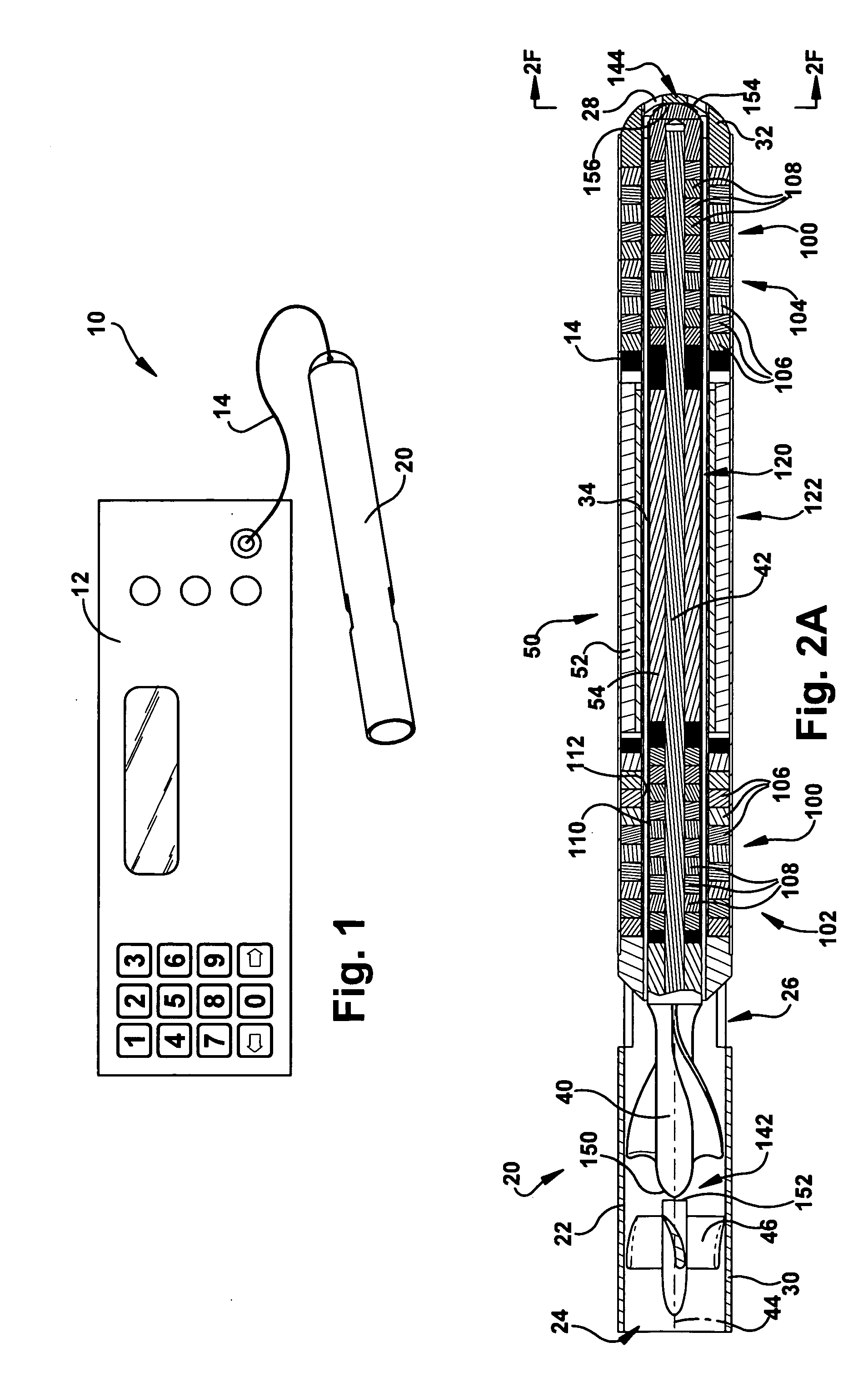
[0012] The present invention also relates to a blood pump that includes a stator assembly including a fluid inlet and a fluid outlet. The pump includes a rotor assembly including an impeller rotatable about an axis to move fluid from the inlet to the outlet. The pump also includes at least one permanent magnet radial bearing for supporting the rotor assemb

Problems solved by technology

Placement of the pumping device, in terms of both size and delivery method, are frequently more critical issues than maximum possible pump output.
The recent advances in adult blood pumping now enable pediatric mechanical circulatory support not previously practical.
This can be attributed to both a lack of good pediatric assist device systems, and the extensive pediatric experience utilizing ECMO for the treatment of respiratory failure.
This is unfortunate because many of the bleeding, thromboembolic, and immune related complications can be attributed to the large surface areas of the oxygenators and the required anticoagulation, as well as high potential for clot formation in flow paths and complement activation by the foreign surfaces.
In addition, ECMO systems restrict patient mobility and are suitable only for short-term support.
While the use of VADs for pediatric circulatory support has been shown to result in significantly fewer long-term complications compared to ECMO support, the development of pediatric VADs remains substantially behind that of adult systems.
To this point, VAD experience has been limited primarily to centrifugal pump based systems, and pulsatile systems that are limited to a paracorporeal configuration.
Due to size constraints, none of these systems are designed to be fully implantable for the majority of children.
For exam

Method used


Image

  • Blood pump
  • Blood pump
  • Blood pump

Examples


second embodiment

[0082] The configuration of the pump head housing 250 of the second embodiment helps facilitate extravascular implementations of the pump 20a. More particularly, the pump head housing 250 helps facilitate discharging blood along the outside diameter of the motor / bearing housing 22a into the outlet cannula 254. The configuration of FIG. 6 permits wash flow in the motor gap 34a through the wash flow ports 28a under the influence of arterial pressure. As an additional feature of the embodiment of FIG. 6, the primary flow, being contained within the outlet cannula 254 next to the motor 50a and motor housing 22a, may also have some enhanced cooling effects on the motor. Since the primary flow of the pump 20a is outside the pump rather than through the motor gap 34a, the motor gap can be kept at a minimum size, which helps reduce the overall diameter and size of the pump.

[0083]FIGS. 7A-7C illustrate intracorporeal extravascular implementations of the pump 20a of FIG. 6. Referring to FIG. ...

third embodiment

[0087] the pump 20b is fit with an outflow sheath 300 for directing the primary mixed flow along the outside of the pump. The outflow sheath 300 has a flexible construction that allows the sheath to be wrapped around an outer surface 302 of the pump 20b during implantation. This is shown in dashed lines at 300′ in FIGS. 8A and 8B. During operation of the pump 20b, the flow expands and unwraps the sheath 300 to the position shown in solid lines at 300 in FIGS. 8A-9. This allows the flow to pass through a radial space 304 defined between the pump 20b and the sheath 300. As shown in FIGS. 8A and 8B, the sheath 300 may include means 320, such as wire bands or a helical coil, that helps limit expansion of the sheath to a desired diameter. The means 320 could, for example, be molded or extruded with the sheath 300 or bonded to the sheath.

[0088] Referring to FIG. 8B, in an alternative configuration, the outflow sheath 300 has an end portion 310 connected with the power cable 14b of the pu...


PUM


Abstract

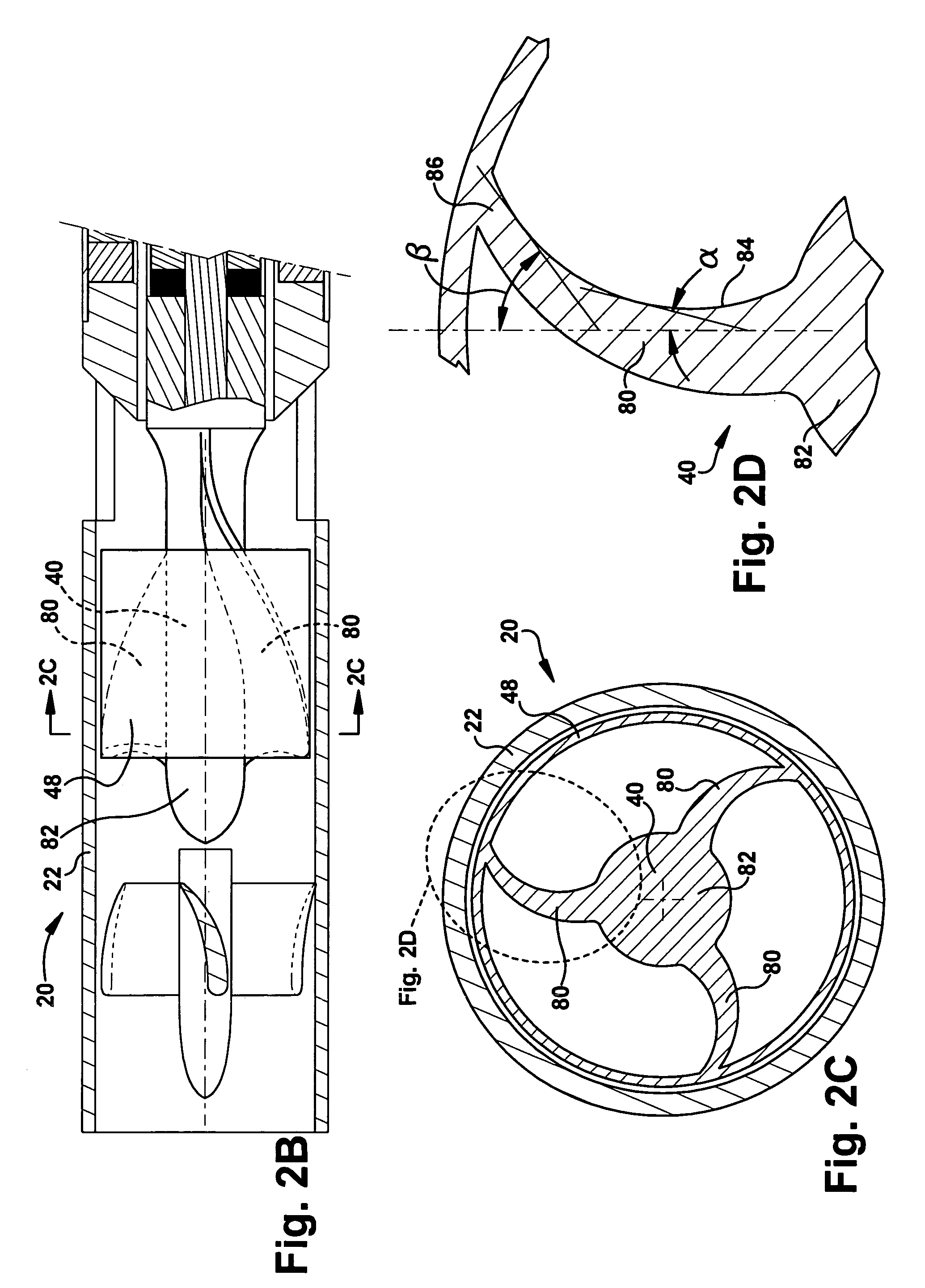
A blood pump (26) includes a stator assembly including a fluid inlet (24) and a fluid outlet (26). A rotor assembly (120) includes an impeller (40) rotatable about an axis (44) to move fluid from the inlet (24) to the outlet (26). A motor (50) imparts rotation of the impeller (40) about the axis (44). The motor (50) includes a motor stator (52) fixed to the stator assembly (122), a motor rotor (54) fixed to the rotor assembly (120), and a radial motor gap (34) between the stator (52) and the rotor (54). The pump (20) is configured to direct a mixed blood flow from the fluid inlet (24) to the fluid outlet (26) and a wash flow through the motor gap (34).

Description

RELATED APPLICATIONS [0001] This application claims the benefit of U.S. Provisional Application No. US 60 / 687,659, filed Jun. 6, 2005.GOVERNMENT RIGHTS [0002] The invention described in this application was supported, at least in part, by United Stated Government Contract Nos. HHSN268200448188C and HL67487 with the National Heart, Lung and Blood Institute and the National Institutes of Health.TECHNICAL FIELD [0003] The present invention relates to a blood pump. More particularly, the present invention relates to an implantable intravascular or intracorporeal extravascular blood pump that may be used as a ventricular assist device. BACKGROUND OF THE INVENTION [0004] In the field of adult cardiac surgery, ventricular assist devices (VADs) are now reaching high levels of success, with the bridge to transplant cases numbering in the thousands. An appreciation has developed that many adult patients can be successfully treated with much lower levels of device flow than were once considere...

Claims


Application Information

Patent Timeline
IPC IPC(8): A61M1/12A61M60/135A61M60/183A61M60/216A61M60/422A61M60/562A61M60/82A61M60/857A61M60/876
CPCA61M1/101A61M1/1015A61M1/1031A61M60/82A61M60/135A61M60/422A61M60/216A61M60/562A61M60/183A61M60/876A61M60/865A61M60/148
Inventor SMITH, WILLIAM A.LORENZ, MARKUSDUDZINSKI, DAVIDCHEN, HSIANG MINGCHAPMAN, PETER A. JR.PRISCO, CHARLES J.VITALE, NICHOLAS G.WEBER, STEPHAN
Owner THE CLEVELAND CLINIC FOUND
Why Eureka
Try Eureka