Retractable finning tool and method of using

a technology of retractable finning and cutting tools, which is applied in the direction of manufacturing tools, transportation and packaging, shearing machines, etc., can solve the problems of reducing the heat transfer performance of tubes, reducing the resistance of tubes, and reducing the heat transfer efficiency of tubes. , to achieve the effect of enhancing the heat transfer performance of tubes, reducing the resistance of tubes, and improving the overall heat transfer performan

Inactive Publication Date: 2007-07-12
WIELAND WERKE AG
View PDF5 Cites 25 Cited by
  • Summary
  • Abstract
  • Description
  • Claims
  • Application Information

AI Technical Summary

Benefits of technology

[0013] This invention provides an improved tool and method for enhancing the heat transfer performance of tubes used in at least all of the above-referenced applications (i.e., flooded evaporators, falling film evaporators, spray evaporators, absorption chillers, condensers, direct expansion coolers and single phase coolers and heaters, used in the refrigeration, chemical, petrochemical and food-processing industries). The inner surface of the tube is enhanced with a plurality of protrusions that significantly reduce tube-side resistance and improve overall heat transfer performance. Formation of protrusions in accordance with this invention can result in the formation of up to five times more surface area along the inner surface of the tube than with simple ridges.
[0014] Certain embodiments of the invention include using a tool, which can be easily added to existing manufacturing equipment, having a cutting edge to cut through the surface of the tube and a lifting edge to lift the surface of the tube to form protrusions. In this way, protrusions are formed without removal of metal from the inner surface of the tube, thereby eliminating debris that can damage the equipment in which the tubes are used.

Problems solved by technology

However, such free flow of heat across the tube is generally thwarted by the resistance to heat transfer.
In general, however, enhancing the inner surface of the tube has proven much more difficult than the outer surface.
Manufacturing heat transfer tubes using known cutting tools can be a delicate and often expensive endeavor.
Thus, as the tool enters the tube, it easily can be damaged.
Additionally, known tools can also be damaged when finning is stopped, then restarted.
These tools often get stuck in the groove created between the finned section and the smooth section of the tube.

Method used


Image

  • Retractable finning tool and method of using
  • Retractable finning tool and method of using
  • Retractable finning tool and method of using

Examples


Embodiment Construction

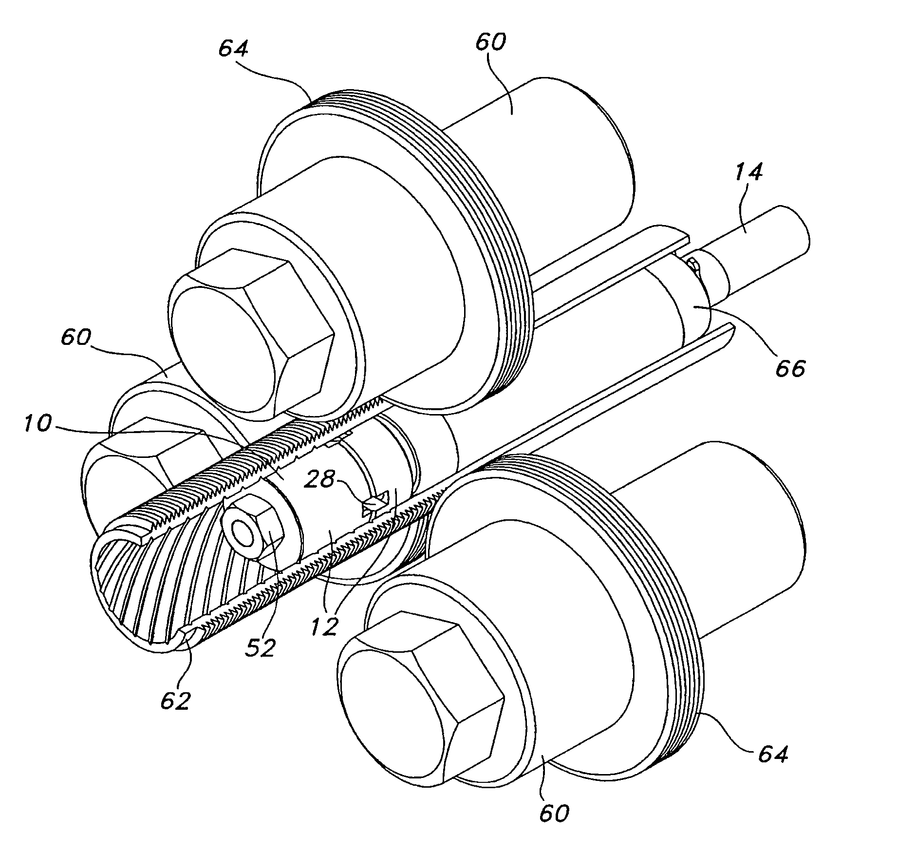
[0032] In order to increase the surface area of the inner diameter of a heat transfer tube, a pattern may be formed on the inner surface of the tube. Protrusions are commonly used for this purpose. One method of forming protrusions involves first forming ridges on the inner surface. The ridges are then cut to create ridge layers, which are subsequently lifted up to form protrusions. This cutting and lifting may be accomplished using tool 10.

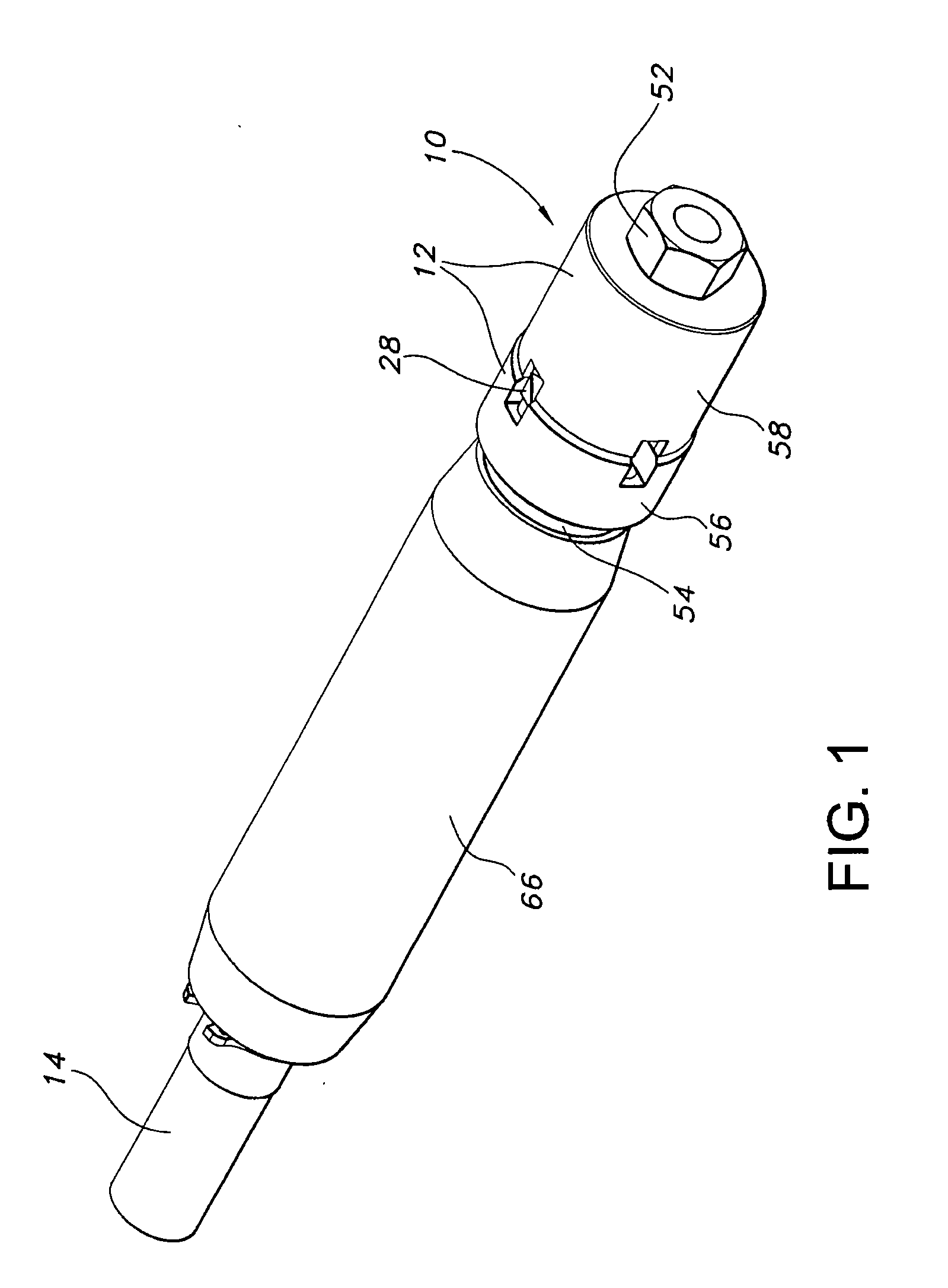
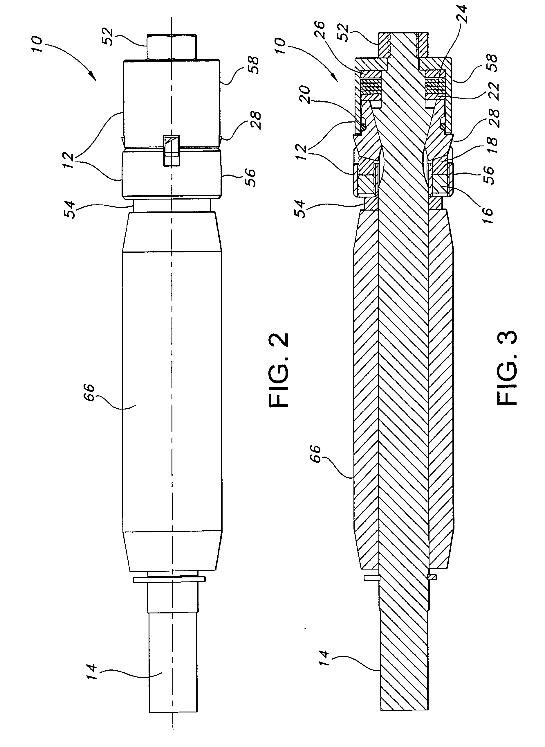
[0033] As shown in FIGS. 1 and 2, tool 10 includes housing 12 and at least one cutting bit 28. The cutting bits 28 are retractable within the housing 12. Tool 10 preferably incorporates shaft 14, which may be connected to a rod (not shown).

[0034] In one embodiment of the invention, the tool 10 includes multiple cutting bits 28. In the example shown in FIG. 1, the tool 10 includes at least four cutting bits 28, although only two are visible. As shown in FIG. 3, cutting bits 28 are held in place in part by ring 20. Ring 20 also holds the cutting ...


PUM

PropertyMeasurementUnit
angleaaaaaaaaaa
angleaaaaaaaaaa
angleaaaaaaaaaa

Abstract

An improved tool and method for enhancing the surface of a heat transfer tube are provided. The tool, which can be easily added to existing manufacturing equipment, includes cutting bits that may be retracted with a housing. The cutting bits include a cutting edge to cut through the surface of a tube and a lifting edge to lift the surface of the tube to form protrusions. A method for enhancing the inner surface of the tube includes mounting a tool on a shaft, positioning the tool in the tube and causing relative rotation and axial movement between the tube and the tool to cut at least partially through at least one ridge formed along the surface of the tube to form ridge layers and lift the ridge layers to form protrusions.

Description

CROSS-REFERENCE TO RELATED APPLICATIONS [0001] This application claims priority to U.S. application Ser. No. 10 / 458,398, filed on Jun. 10, 2003, U.S. Patent Application Ser. No. 60 / 570,858, filed May 13, 2004 and U.S. patent application Ser. No. 10 / 972,734, filed on Oct. 25, 2004, the entirety of each of which is incorporated by reference.BACKGROUND OF THE INVENTION [0002] 1. Field of the Invention [0003] The invention relates generally to a tool for forming protrusions on the inner surface of a heat transfer tube and a method for using the tool. [0004] 2. General Background of the Invention [0005] This invention relates to heat transfer tubes having an enhanced inner surface to facilitate heat transfer from one side of the tube to the other. Heat transfer tubes are commonly used in equipment, such as, for example, flooded evaporators, falling film evaporators, spray evaporators, absorption chillers, condensers, direct expansion coolers, and single phase coolers and heaters, used in...

Claims


Application Information

Patent Timeline
Patent Type & Authority Applications(United States)
IPC IPC(8): B23P15/26B23D21/00B21D53/06
CPCB21C37/207Y10T29/5122Y10T29/5147Y10T408/03Y10T82/10Y10T29/49385Y10T29/49995Y10T408/85843Y10T29/5199Y10T29/49377B21J5/068
Inventor THORS, PETURKOUSE, BRUCEMINSHALL, GERRY
Owner WIELAND WERKE AG
Why Eureka
Try Eureka