Soldering driving elements in LCD panels

a technology of driving elements and liquid crystal displays, which is applied in the direction of soldering devices, instruments, auxillary welding devices, etc., can solve the problems of increasing display manufacturing time, slow technique, and worker exposure to illnesses, so as to improve display panel manufacturing productivity and reduce the exposure of factory workers

Inactive Publication Date: 2007-07-12
SAMSUNG ELECTRONICS CO LTD
View PDF3 Cites 31 Cited by
  • Summary
  • Abstract
  • Description
  • Claims
  • Application Information

AI Technical Summary

Benefits of technology

[0006]In accordance with the exemplary embodiments thereof described herein, the present invention provides apparatus and methods for soldering LED driving e

Problems solved by technology

However, this technique is slow and substantially increases display manufacturing time.
Further,

Method used


Image

  • Soldering driving elements in LCD panels
  • Soldering driving elements in LCD panels
  • Soldering driving elements in LCD panels

Examples


Embodiment Construction

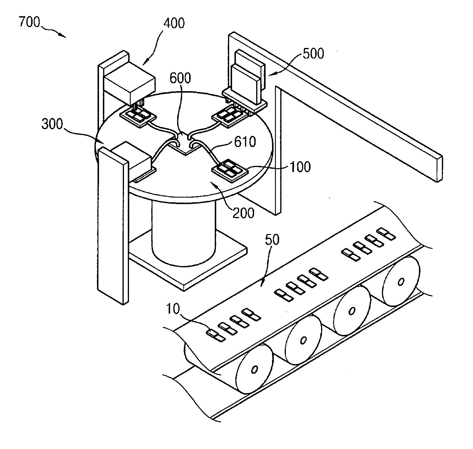
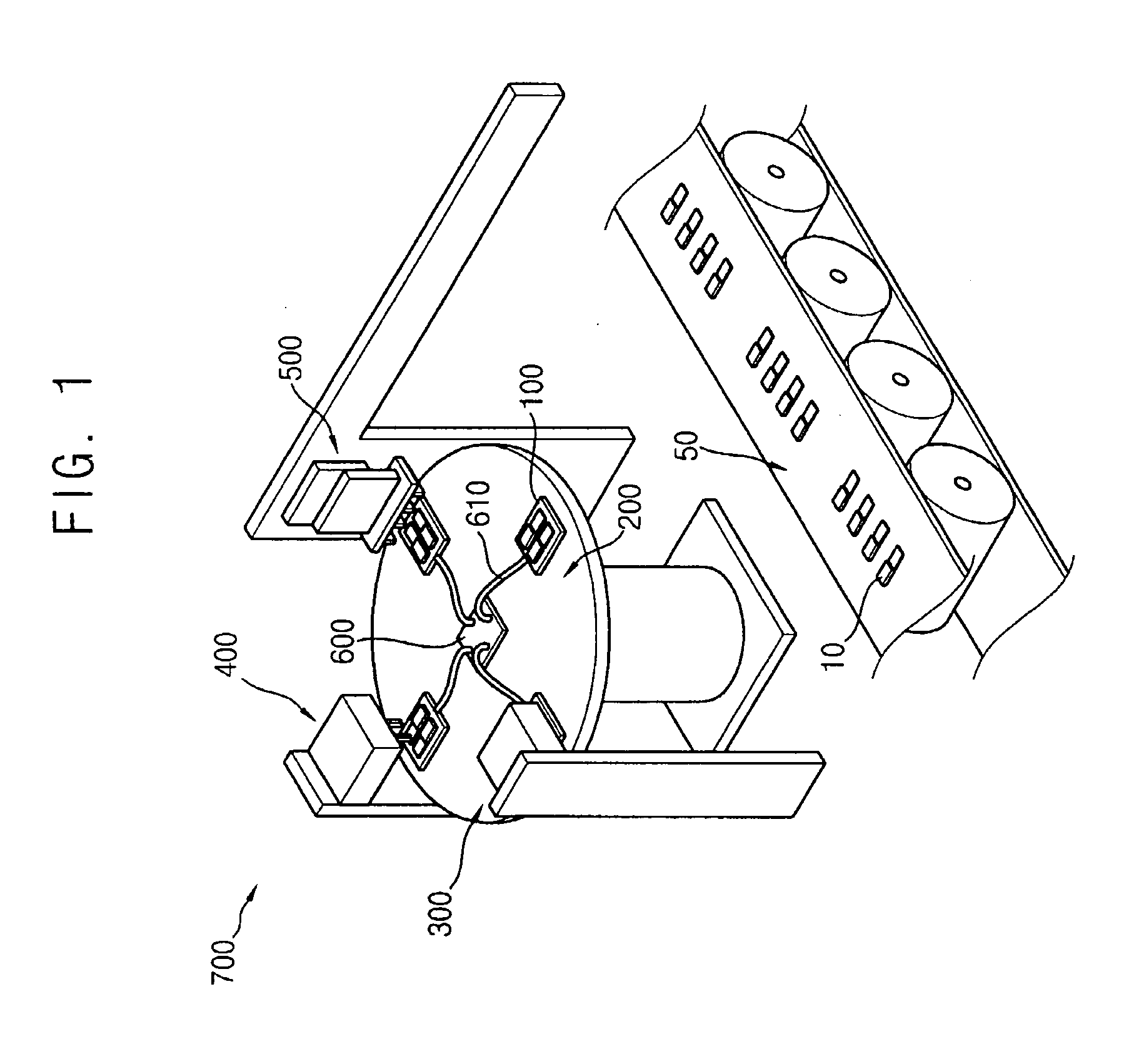
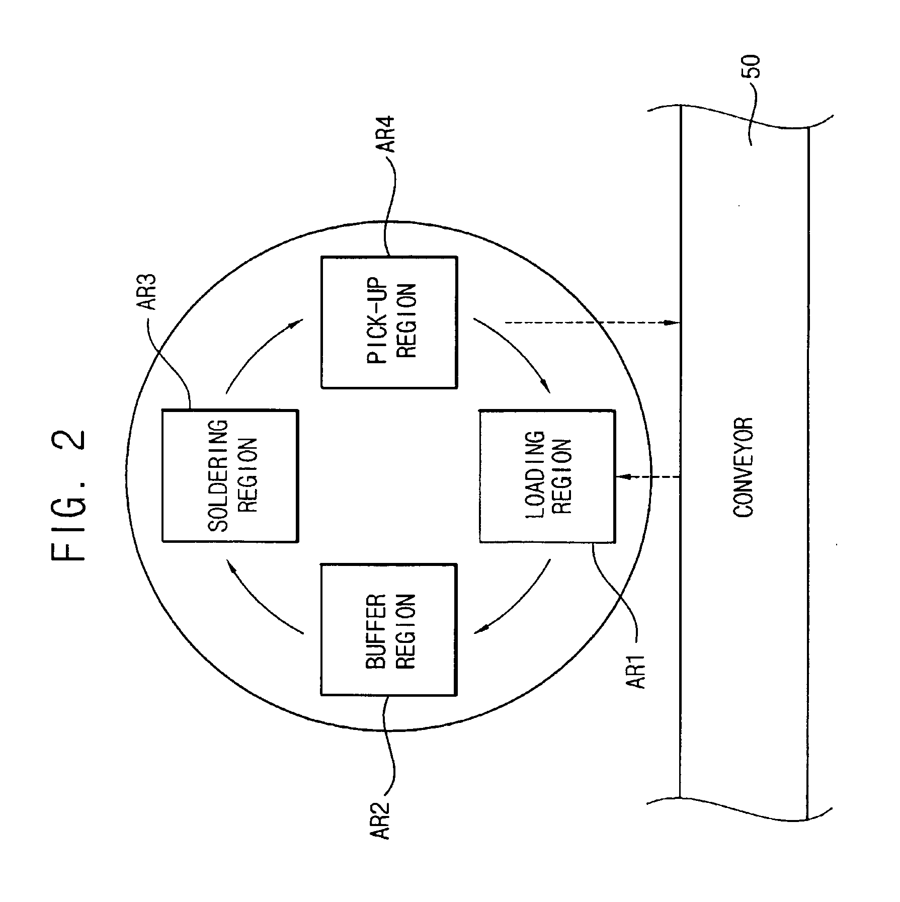
[0021]The invention is described more fully hereinafter with reference to the accompanying drawings, in which embodiments of the invention are shown. This invention may, however, be embodied in many different forms and should not be construed as limited to the embodiments set forth herein. Rather, these embodiments are provided so that this disclosure will be thorough and complete, and will fully convey the scope of the invention to those skilled in the art. In the drawings, the size and relative sizes of layers and regions may be exaggerated for clarity. It will be understood that when an element or layer is referred to as being “on,”“connected to” or “coupled to” another element or layer, it can be directly on, connected or coupled to the other element or layer or intervening elements or layers may be present. In contrast, when an element is referred to as being “directly on,”“directly connected to” or “directly coupled to” another element or layer, there are no intervening elemen...


PUM

PropertyMeasurementUnit
Angleaaaaaaaaaa
Angleaaaaaaaaaa
Flexibilityaaaaaaaaaa

Abstract

An apparatus and method for soldering an LED driving element to an LCD panel includes a panel holding unit, a rotating unit and a soldering unit. The panel holding unit holds the display panel. The rotating unit supports the panel holding unit at initial radial and angular positions relative to a center of rotation of the rotating unit and rotates the holding unit in a horizontal plane about the center of rotation to selected angular positions relative thereto. The soldering unit is disposed above the rotating unit at the initial radial position and at a first angular position relative to initial angular position of the holding unit, and is operable to solder the driving element of the display panel held by the panel holding unit when the rotating unit rotates the panel holding unit to the first angular position. The apparatus and method provide improved display panel productivity.

Description

RELATED APPLICATIONS[0001]This application claims priority of Korean Patent Application No. 2006-01876, filed Jan. 6, 2006, the entire disclosure of which is incorporated herein by reference.BACKGROUND[0002]This invention relates to methods and apparatus for soldering light emitting diode (LED) driving elements in liquid crystal display (LCD) panels to improve panel productivity.[0003]In general, LCDs are flat panel display devices that display an image using the electro-optical characteristics of liquid crystals. LCDs provide many features and advantages relative to other types of display devices, such as a thinner display panel, lighter weight, lower power consumption, lower driving voltages, and others. Accordingly, LCDs have been widely adopted as the display device of choice in a number of fields, e.g., large screen television sets, computer monitors, mobile communication terminals, and the like.[0004]An LCD includes an LCD panel and a backlight assembly. The LCD panel displays...

Claims


Application Information

Patent Timeline
IPC IPC(8): H05K3/34B23K37/00
CPCB23K3/087Y10T29/53187Y10T29/49144B23K2201/42B23K2101/42H01L23/48G02F1/13
Inventor JEON, JAE-WOOCHOI, HYUN-GYUPARK, HEE-YOUNGKANG, HO-JEONG
Owner SAMSUNG ELECTRONICS CO LTD
Why Eureka
Try Eureka