

Hub unit with sensor
- Summary
- Abstract
- Description
- Claims
- Application Information
AI Technical Summary
Benefits of technology
Problems solved by technology
Method used
Image

Examples
first embodiment
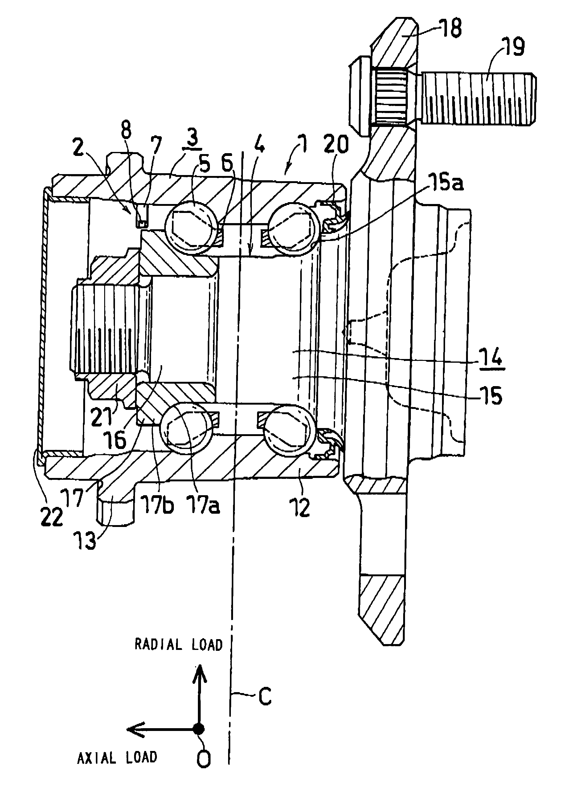
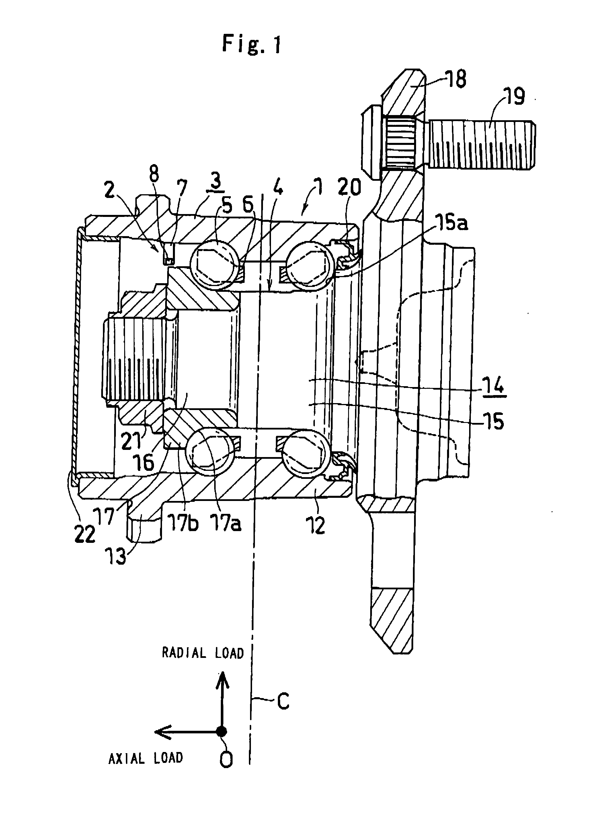
[0052]FIG. 1 shows a hub unit with a sensor of a first aspect of the present invention. In the following explanation, left and right will be referred to as the left and right of FIG. 1. Note that the left is the inside of the vehicle, and the right is the outside of the vehicle.
[0053] The hub unit with a sensor comprises a hub unit (1) and a sensor device (2) for detecting the rotation thereof and the tire grounding load.
[0054] The hub unit (1) includes a body-side raceway member (3) which is to be fixed to the vehicle body side, a wheel-side raceway member (4) to which a wheel is to be mounted, a plurality of balls (5) which are rolling elements disposed in two rows between the both members (3) and (4), and cages (6) for holding the balls (5) of the respective rows.
[0055] The body-side raceway member (3) has an outer ring (fixed ring) function of a bearing, including a cylindrical part (12) in which two rows of outer ring raceways are formed on the inner peripheral face, and a fl...
second embodiment
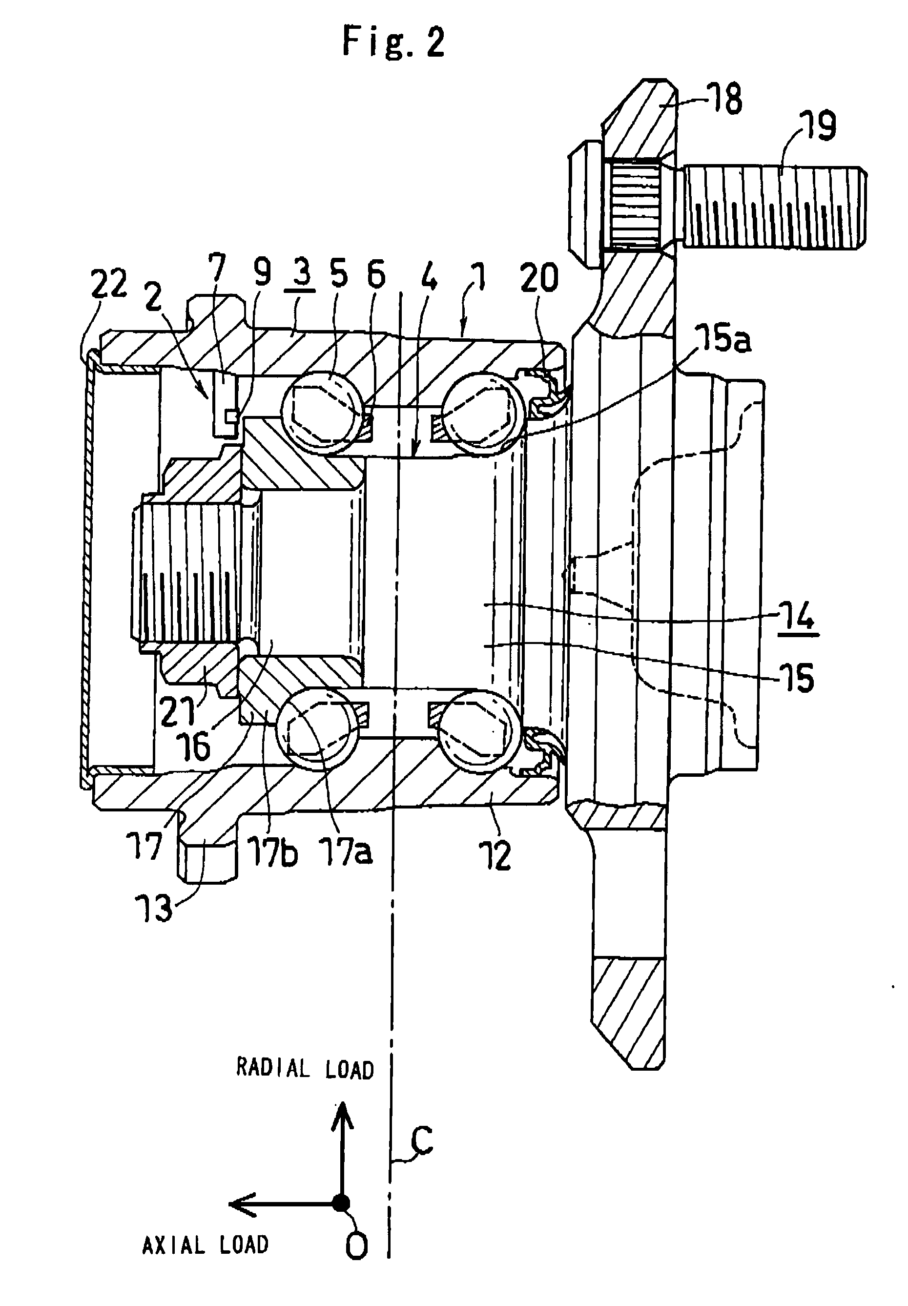
[0064] The sensor device (2) of the hub unit with the sensor of the second embodiment includes a support member (7) mounted to the body-side raceway member (3), a magnetostrictive sensor (9) mounted to the support member (7), and a processing means (not shown in FIG. 2, see FIG. 7) for processing output of the magnetostrictive sensor (9). The magnetostrictive sensor (9) is a magnetic impedance sensor, and the sensing surface thereof is made to face the left end face of the uppermost part of the inner ring shoulder part (17b) of the wheel-side raceway member (4) from the left side in the axial direction so as to measure the tensile strain on the outer peripheral face of the uppermost part of the inner ring (17) of the wheel-side raceway member (4). In this way, by disposing the magnetostrictive sensor (9) on just left side of the uppermost part of the inner ring shoulder part (17b) so as to detect the tensile strain in the axial direction of the inner ring (17), a large inverse magne...
third embodiment
[0067]FIG. 3 shows the hub unit with a sensor of the first aspect of the present invention.
[0068] The hub unit with a sensor comprises a hub unit (31) and a sensor device (32) for detecting the rotation thereof and the grounding load.
[0069] The hub unit (31) includes a body-side raceway member (33) to be fixed on the vehicle body side, a wheel-side raceway member (34) to which a wheel is to be mounted, a plurality of balls (35) which are rolling elements disposed in two rows between the both members (33) and (34), and cages (36) for holding the respective rows of balls (35).
[0070] The body-side raceway member (33) has an outer ring (fixed ring) function of a bearing, and includes a cylindrical part (42) in which two rows of outer ring raceways are formed on the inner peripheral face, and a flange part (43) which is provided near the left end part of the cylindrical part (42) and mounted with bolts to a suspension device (vehicle body).
[0071] The wheel-side raceway member (34) con...
PUM
 Abstract
Description
Claims
Application Information