Ion beam delivery equipment and an ion beam delivery method

a technology of ion beam and equipment, which is applied in the field of ion beam delivery equipment and ion beam delivery method, can solve the problems of difficult to efficiently treat a large number of patients, and achieve the effect of increasing the number of patients that can be treated using one modulation wheel

Active Publication Date: 2007-07-12
HITACHI LTD +1
View PDF3 Cites 24 Cited by
  • Summary
  • Abstract
  • Description
  • Claims
  • Application Information

AI Technical Summary

Benefits of technology

[0010] It is an objective of the present invention to provide an ion beam delivery equipment and an ion beam delivery method, which can increase the number of patients treatable using one wheel having a thickness varied in the rotating direction to change energy of the ion beam passing the wheel.
[0015] According to the present invention, since the modulation wheel has the thickness varied in the rotating direction to change energy of the ion beam passing the wheel, the number of patients treatable using one modulation wheel can be increased.

Problems solved by technology

This has invited the necessity of forming and preparing a different RMW for each patient and replacing the RMW whenever the patient is changed, and hence has caused a difficulty in efficiently treating a large number of patients.

Method used


Image

  • Ion beam delivery equipment and an ion beam delivery method
  • Ion beam delivery equipment and an ion beam delivery method
  • Ion beam delivery equipment and an ion beam delivery method

Examples


first embodiment

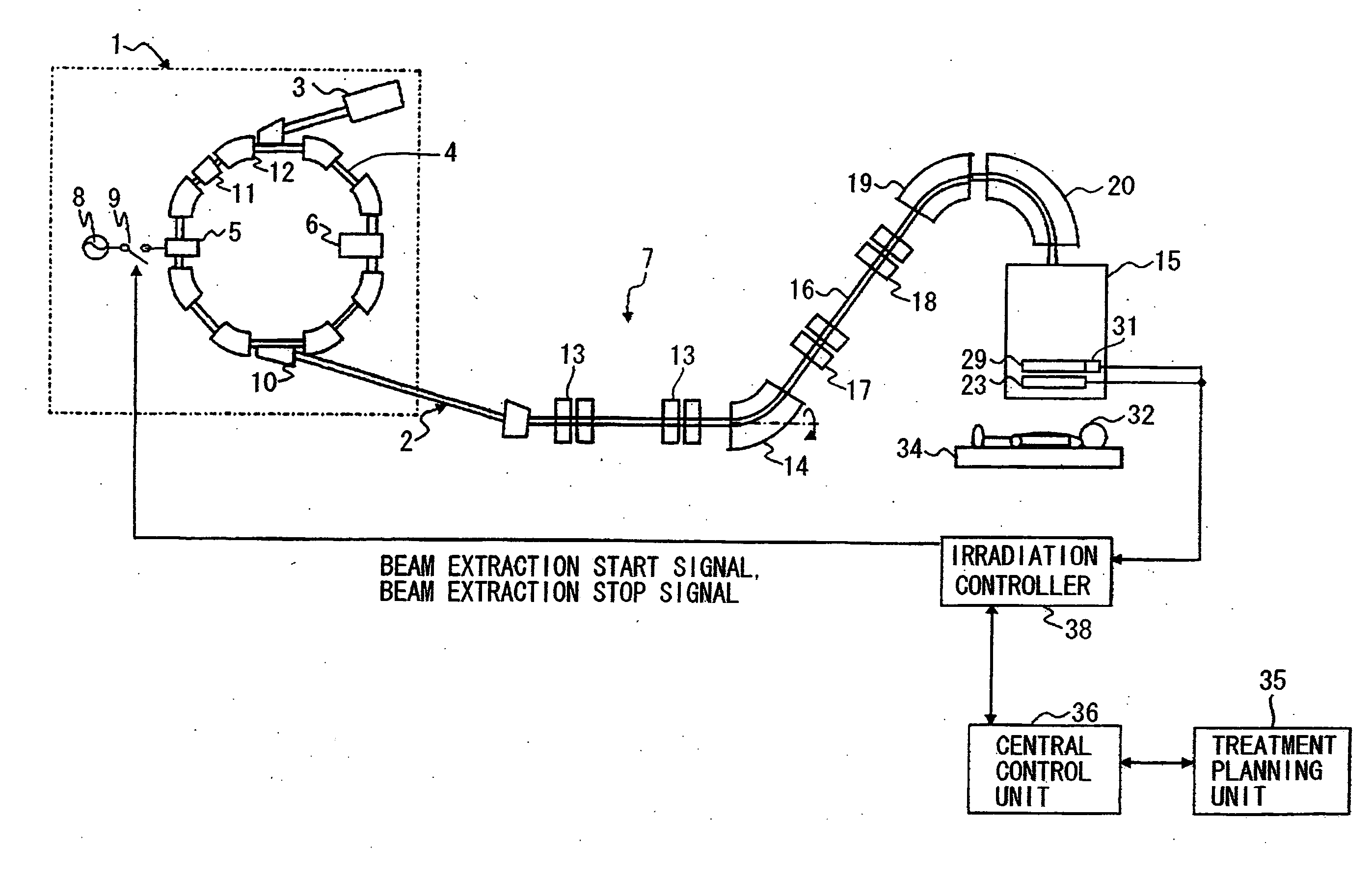
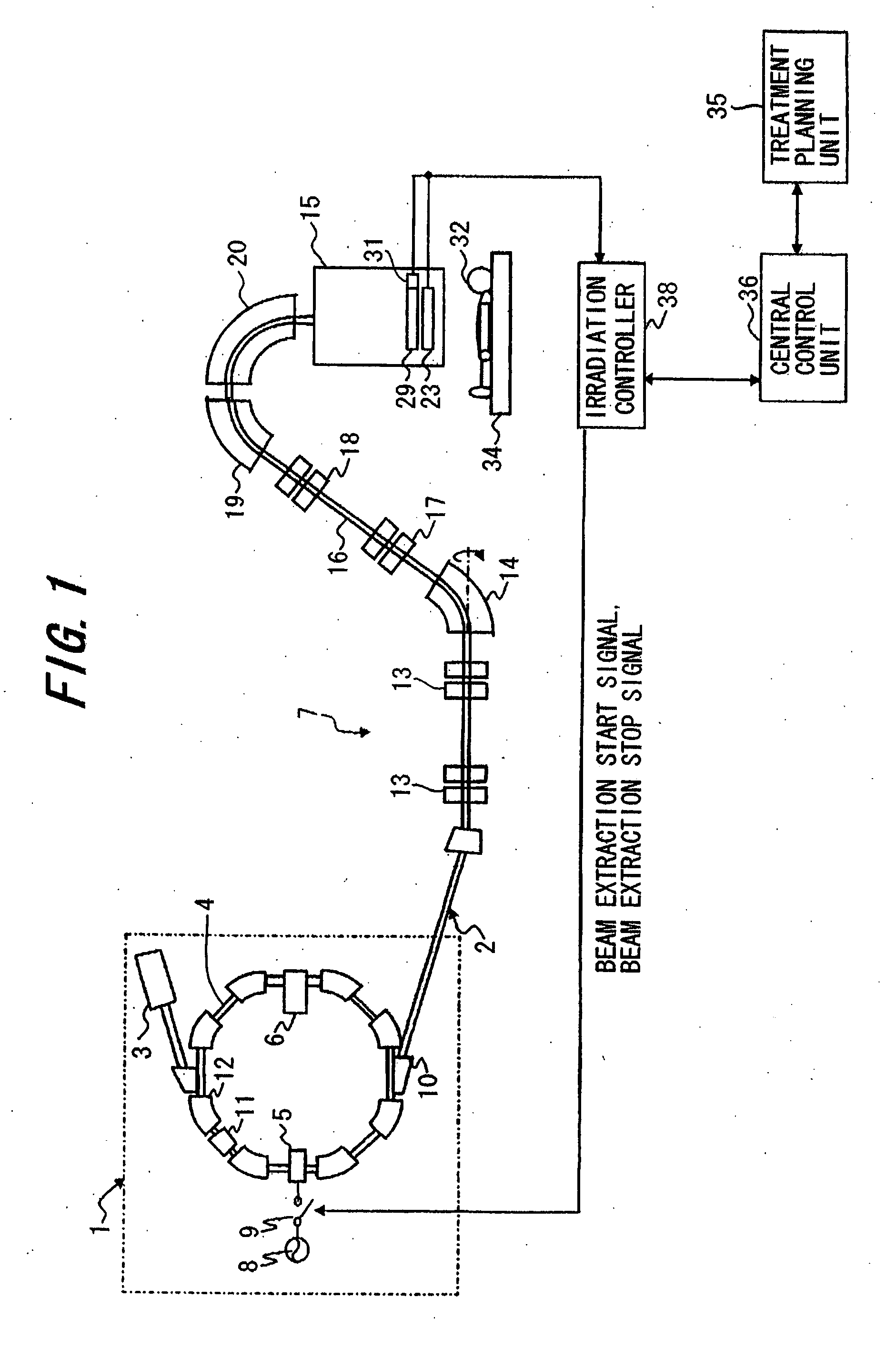
[0030] Proton beam delivery equipment 7 as ion beam delivery equipment of this embodiment comprises, as shown in FIG. 1, a beam generator 1, a beam transport system 2, and an beam delivery nozzle 15, the latter two being connected downstream of the beam generator 1.

[0031] The beam generator 1 comprises an ion(proton) source (not shown), a pre-accelerator 3, and a synchrotron 4 serving as a main accelerator. The synchrotron 4 includes an RF-applying device 5 having a pair of electrodes and an RF-accelerating cavity 6. The RF-applying device 5 and the RF-accelerating cavity 6 are installed on an orbit of a circulating ion beam. A first RF-power supply 8 is connected to the electrodes of the RF-applying device 5 through an on / off switch 9. A second RF-power supply (not shown) for applying an RF power to the RF-accelerating cavity 6 is separately provided. Ions (e.g., proton ions (or carbon ions)) generated by the ion source are accelerated by the pre-accelerator 3 (e.g., a linear acce...

second embodiment

[0065] Proton beam delivery equipment according to a second embodiment, i.e., another embodiment of the present invention, will be described below. In the proton beam delivery equipment of this second embodiment, an RMW 67 shown in FIG. 10 is substituted for the RMW 29 installed in the beam delivery nozzle 15 in the proton beam delivery equipment 7 of the first embodiment. The other construction of the proton beam delivery equipment of this second embodiment is the same as that of the proton beam delivery equipment 7. In the proton beam delivery equipment of this second embodiment, as shown in FIG. 11, the beam extraction-on / off control is performed for each stepped portion (plane area) of the RMW 67.

[0066] The RMW 67 includes one blade 68 having a plurality of plane areas 43 formed such that a thickness of each plane area in the axial direction is increased step by step from the opening 42 having a thickness being 0 to a top portion 70 having a maximum thickness in a direction opp...


PUM


Abstract

The invention is intended to increase the number of patients treatable using one wheel having a thickness varied in the rotating direction to change energy of an ion beam passing the wheel. Ion beam delivery equipment for irradiating an ion beam to a patient for treatment comprises a beam generator for producing and accelerating the ion beam, an beam delivery nozzle including a range modulation wheel which has a predetermined thickness distribution in the rotating direction and is rotated on a travel passage of the ion beam generated from the beam generator to control a range of the ion beam, and an irradiation controller for controlling the beam producing and accelerating operation of the beam generator in accordance with the phase of rotation of the range modulation wheel.

Description

BACKGROUND OF THE INVENTION [0001] 1. Field of the Invention [0002] The present invention relates to ion beam delivery equipment and ion beam delivery method, which are used to produce and deliver ion beam, e.g., proton or carbon ions, to a tumor for treatment. [0003] 2. Description of the Related Art [0004] There is known a method for delivering ion beam, e.g., proton or carbon ions, to a tumor, such as a cancer, in the body of a patient. The ion beam delivery equipment for such treatment comprises an ion beam generator to produce the said ion beam and accelerate it to a needed energy, a beam transport system, and an beam delivery nozzle. An ion beam accelerated by the beam generator reaches the beam delivery nozzle, which is installed in a rotating gantry to monitor and shape the therapeutic radiation field, through a first beam transport system and a second ion beam transport system, the latter being installed in the rotating gantry. The ion beam reached the beam delivery nozzle ...

Claims


Application Information

Patent Timeline
Patent Type & Authority Applications(United States)
IPC IPC(8): H01J37/08
CPCA61N5/10A61N2005/1087H05H7/04G21K5/04A61N2005/1095
Inventor HIRAMOTO, KAZUOAKIYAMA, HIROSHIYANAGISAWA, MASAKIFUJIMAKI, HISATAKASMITH, ALFREDNEWHAUSER, WAYNE
Owner HITACHI LTD
Why Eureka
Try Eureka