Paper sheet treating device

Inactive Publication Date: 2007-07-12
MAX CO LTD
View PDF7 Cites 6 Cited by
  • Summary
  • Abstract
  • Description
  • Claims
  • Application Information

AI Technical Summary

Benefits of technology

[0013] Therefore, the present invention has an object to provide a paper sheet treating device which can perform high-speed treatments with a simple constitution and which is excellent in the positioning precision of paper sheets and in the feeding stability of the sheets.
[0014] Another object is to provide a paper sheet treating device which is equipped with an after treatment device such as a punching device having a cycle time period shortened to raise the treating speed.
[0015] Still another object is to provide a paper sheet treating device which is equipped with a punching device eliminating the deviation in the positional relation among the punches of a punching unit, a die and paper sheets thereby to prevent the positional errors of punched holes.
[0019] Moreover, the sheet treating device may also be constituted such that positioning plates capable of widening / narrowing the mutual spacing and a drive mechanism therefor are disposed on the two right and left sides of the sheet table so that the sheet fed onto the sheet table may be interposed between the two right and left sides by the positioning plates thereby to correct the positional deviation and the positions in the transverse direction.
[0027] Moreover, the sheet treating device may also be constituted such that the punching device can mount the punching unit having the punches and the die removably on the punching device body, such that a sheet positioning mechanism is provided for correcting the position of the sheet in the direction perpendicular to the transfer, and such that the punching device body includes read means for reading the positional deviation information, and control means for controlling the sheet positioning mechanism in accordance with the positional deviation information read, thereby to correct the position of the sheet in the direction perpendicular to the transfer so that the positional deviations of the punches and the die are eliminated.

Problems solved by technology

The means is so complicated in its control system as to require a control unit capable of high-speed operations so that it has a high cost.
However, the abutting face of the sheet is not flat so that its positioning precision is poor thereby to raise a problem that the sheet position is liable to disperse.
In the constitution for positioning the sheet by bringing its leading end into abutment against a fence for a positioning reference, moreover, the positioning precision is satisfactory, but the sheet is reversely discharged after punched or stapled, so that the feed mechanism is complicated to invite a reduction in the treating speed.
However, the punching device constituted to keep the punches at the upper standby position by the spring takes a considerable time for the descending stroke because it pushes down the punches against the spring force.
Especially the case of multiple punches of several tens has a high punching load and a larger weight than that of the two-hole punches so that it requires a power source of a high capacity and takes a cost high.
In the ascending stroke, moreover, the punches are promptly lifted by the spring bias but have a large inertia biased by the spring thereby to raise a problem that they take a long time till they stop.
Due to the tolerances or assembly errors of the individual parts composing the punching unit, however, the positional relations between the paper sheet and the punches of the punching unit, which are positioned by the sheet feed mechanism or the positioning mechanism on the body side, are not fixed when the punching unit is mounted on the punching device, thereby to cause errors in the positions of the punched holes.

Method used


Image

  • Paper sheet treating device
  • Paper sheet treating device
  • Paper sheet treating device

Examples


embodiments

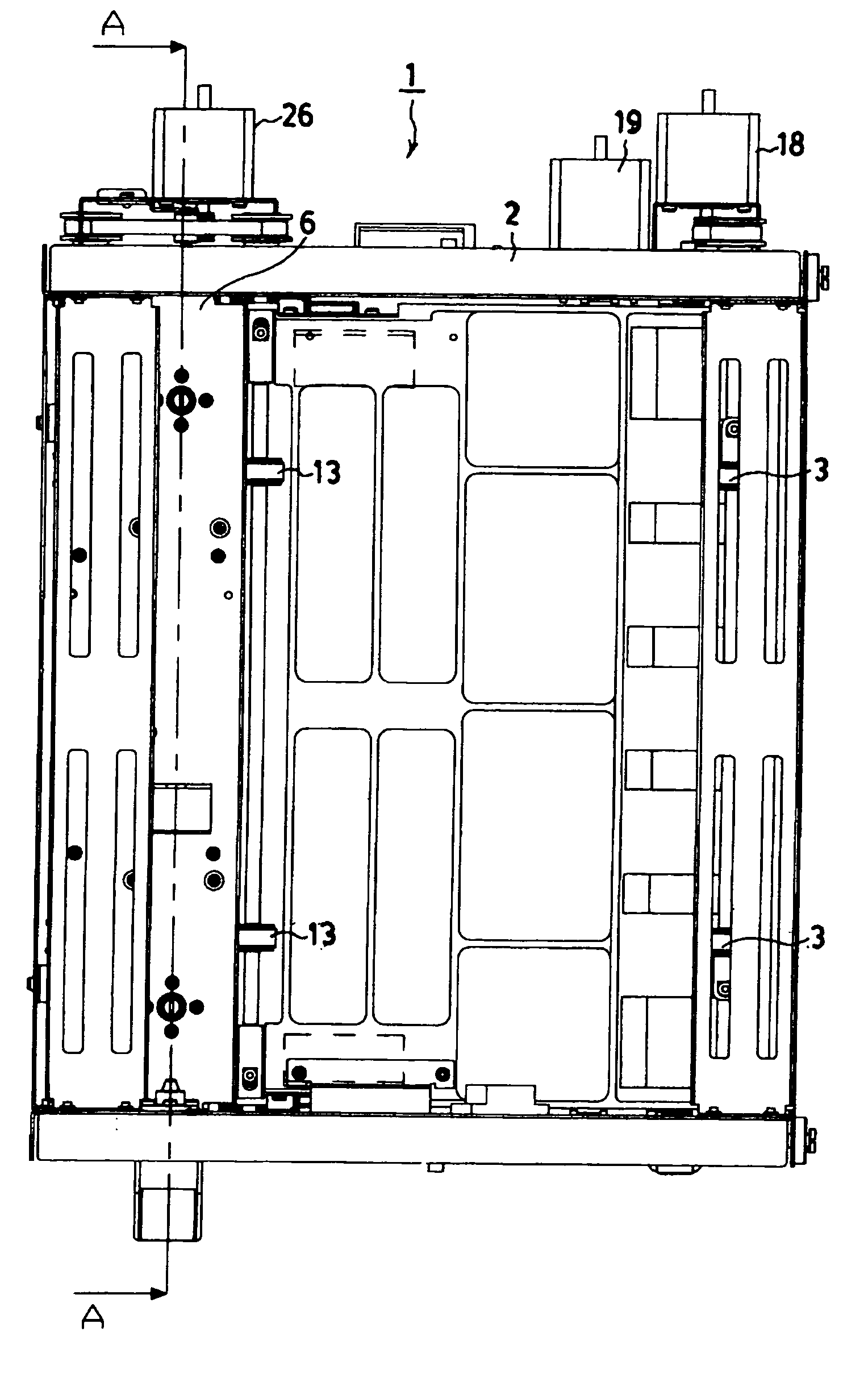
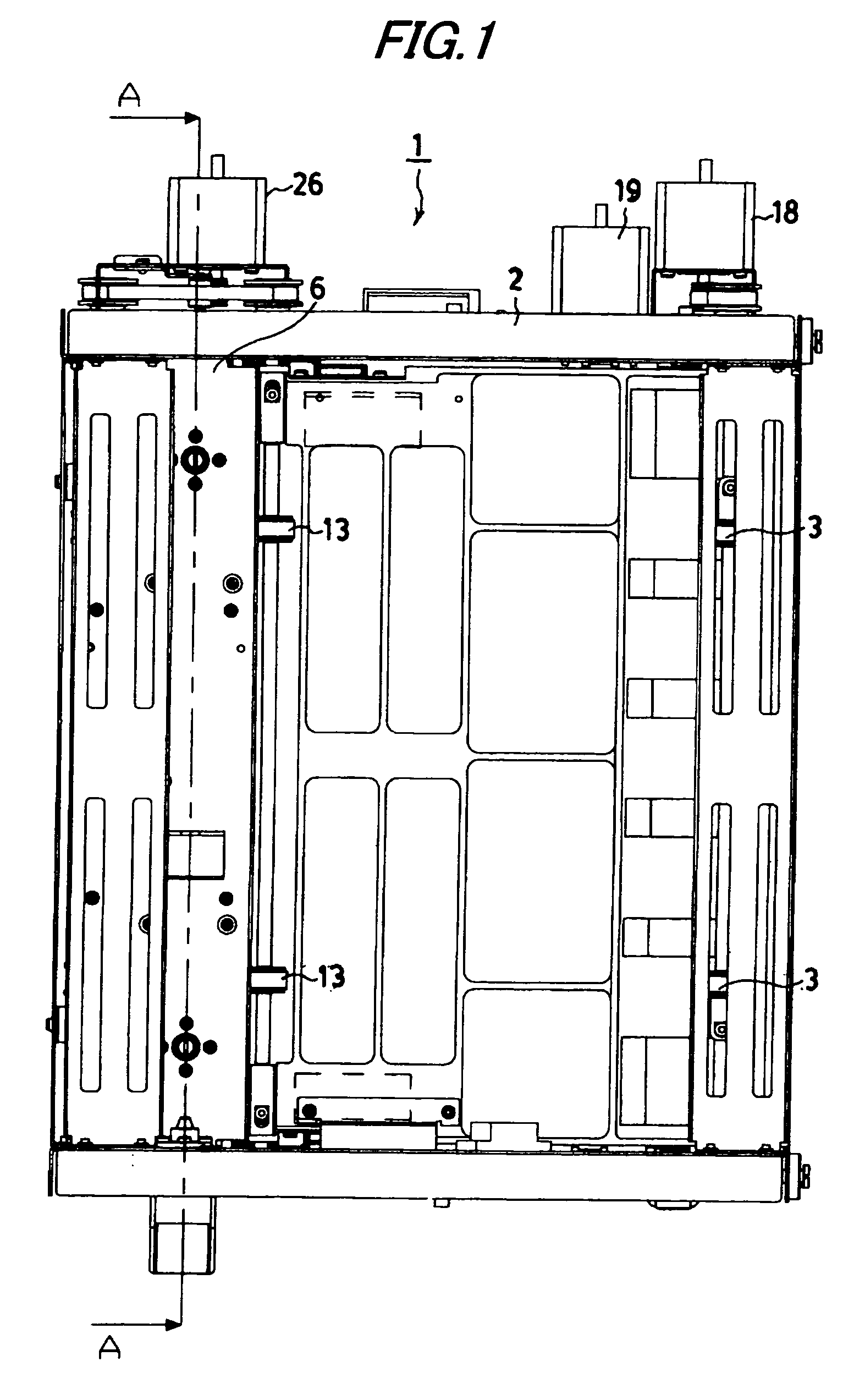
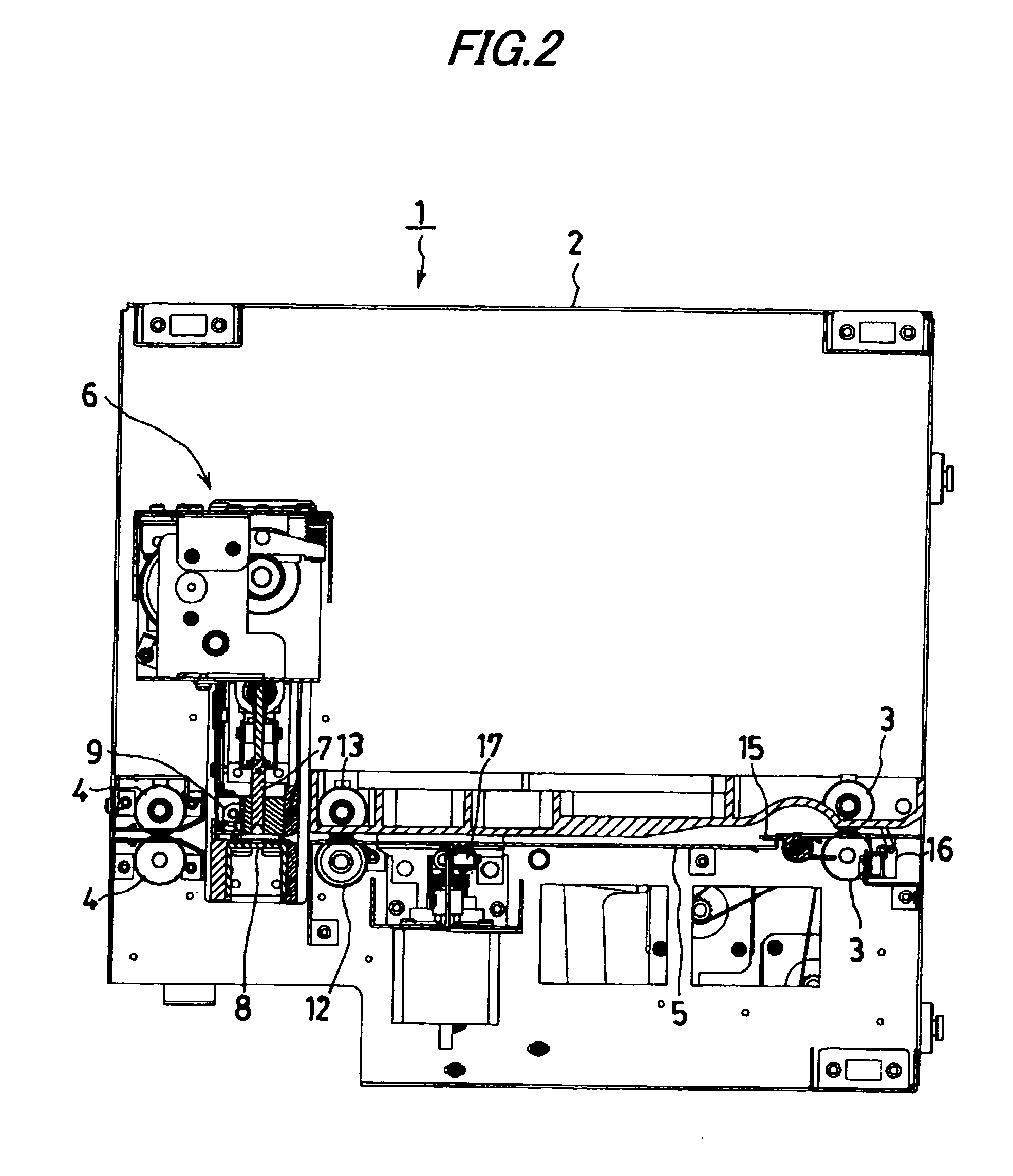
[0053]FIG. 1 to FIG. 4 show a sheet treating device which is equipped with a punching device 1 as an aftertreatment device. As shown in FIG. 2, the punching device 1 is constituted by arranging a pair of upper and lower feed rollers 3 in the front portion (as located on the right side) of a frame 2, as shown, and by arranging a pair of upper and lower discharge rollers 4 in a rear portion so that a paper sheet discharged from the (not-shown) copying mechanism unit is pulled by the feed rollers 3 and sent rearward on a horizontal sheet table 5 and is punched by a multi-hole punching unit 6 arranged just upstream of the discharge roller 4 and then discharged rearward by the discharge roller 4.

[0054] The punching unit 6 is equipped with a 30-hole type punch 7, a die plate 8, and a closing type fence 9 acting as a sheet stopper on the downstream side (as located on the left side in FIG. 2) of the sheet feed. The punching unit 6 mounts a punch driving motor 10 and a fence driving soleno...


PUM


Abstract

A closing type fence 9 is disposed at the downstream side leading end of a sheet table 5 of a punching device 1. Jogging rollers 12 having a torque limiter are arranged just upstream of a punching unit 6. The sheet, as fed into the sheet table by feed rollers 3, is pushed onto the closing type fence by the jogging rollers and is interposed between right and left positioning plates so that it is precisely positioned. When the punching treatment by the punching unit is executed, the closing type fence is opened so that the sheet is discharged by the jogging rollers and discharge rollers 4.

Description

TECHNICAL FIELD [0001] The present invention relates to a paper sheet treating device associated with a copying machine or a printer device for performing an aftertreatment such as a punching treatment or a stapling treatment and, more particularly, to a paper sheet treating device which is improved in a treating precision and raised in a treating speed. BACKGROUND ART [0002] There has been known either a composite device for stapling printed paper sheets by combining an electric stapler with the copying machine or the printer device, or a composite device in which a punching device is combined so as to operate a punching treatment to the printed paper sheets so that a binder can be attached to the sheets. The composite device of this kind is required for a high precision in a position control or registration of paper sheets at the time when the sheets are fed after printed to the stapler or the punching device for the stapling or punching treatment, and for a high speed not inferio...

Claims


Application Information

Patent Timeline
IPC IPC(8): B65H39/00B65H31/36B26D7/01B26F1/02B65H31/34B65H37/00
CPCB26D7/015B65H2801/27B65H31/36B26F1/02B65H37/00
Inventor HASEGAWA, TAKAO
Owner MAX CO LTD
Why Eureka
Try Eureka