
Axially actuating device having elastic joining portion

a technology of axial actuation and elastic joining, which is applied in the direction of magnetic bodies, printers, cameras focusing arrangements, etc., can solve the problems of increasing the number of parts, increasing the volume and weight, and damaging the inside mechanism or the function is not desirable, so as to reduce the manufacturing cost and eliminate the problem of assembling

Inactive Publication Date: 2007-07-12
IND TECH RES INST
View PDF10 Cites 22 Cited by
  • Summary
  • Abstract
  • Description
  • Claims
  • Application Information

AI Technical Summary

Benefits of technology

The present invention is an axially actuating device that uses an elastic joining portion to carry and actuate an object. The device includes a fixed portion, a moving portion, and a joining member that combines the fixed and moving portions. The joining member is made of a flexible and rigid non-metallic composite material that is joined to the fixed and moving portions using a molding technique. This reduces manufacturing costs and eliminates assembly problems. The elastic joining member ensures that the object moves axially without any deflection and has efficacy in limiting the displacement of the moving portion. It also protects the device from damage and functional impairment. The invention has various applications, such as in a miniature voice coil motor used in a cell phone camera.

Problems solved by technology

Generally, driving devices that are convenient for carrying along and available for be used at any time have the characteristics of being small, light, and chic, and on the other aspect, it is easily dropped off due to incautiousness, which thus damages the inside mechanism or the function is not desirable.
Therefore, the dependence on a protecting device is essentially increased, but the addition of the protecting device results in increasing of the number of parts, and thus increasing the volume and weight and becoming inconvenient for reserving, so that the original advantages are not existed any longer.
Moreover, from the designing view of being light, thin, short, and small, the decrease in size enhances the difficulty in assembling, so that the cost is increased.
However, the most significant disadvantage of the leaf spring-type joining device lies in that, a small amount of rotating movement is made in the axial direction, and the shock proofing efficacy is not provided, and thus not suitable for a product that is liable to be dropped out.

Method used


Image

  • Axially actuating device having elastic joining portion
  • Axially actuating device having elastic joining portion
  • Axially actuating device having elastic joining portion

Examples


Embodiment Construction

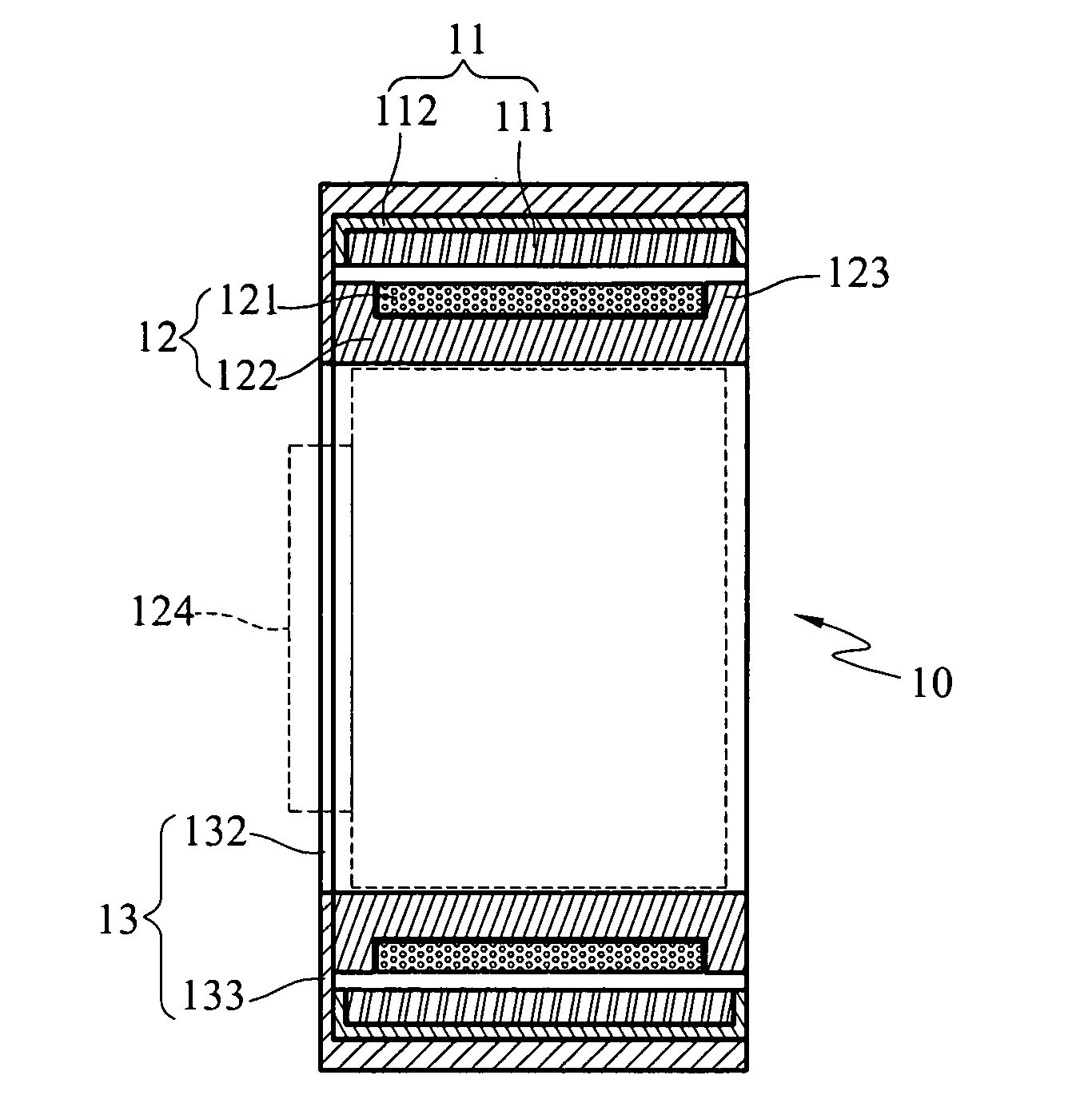
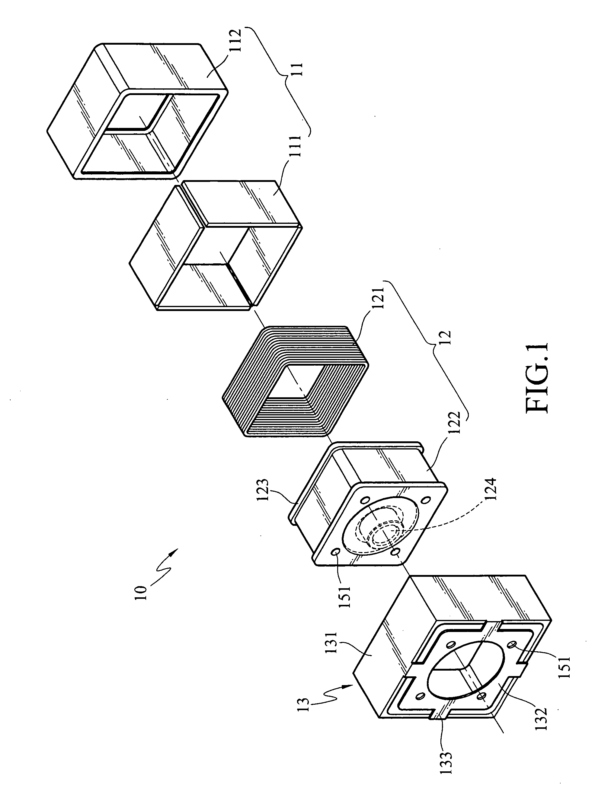
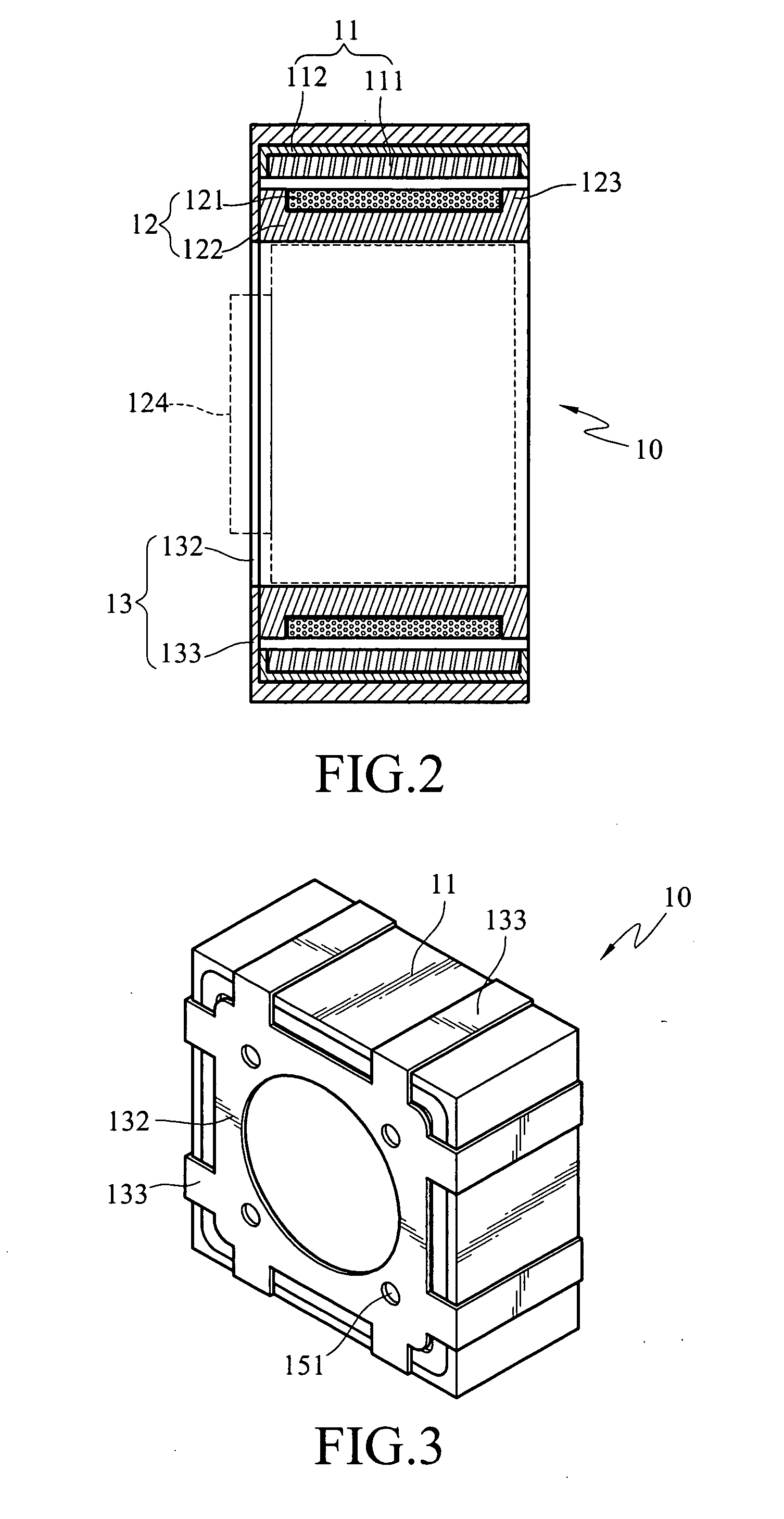
[0026]FIG. 1 is an exploded stereogram of an embodiment of an axially actuating device 10 having an elastic joining portion of the present invention. FIG. 2 is an assembled cross-sectional view of an embodiment of the axially actuating device 10 having an elastic joining portion of the present invention. FIG. 3 is a stereogram of an embodiment of the axially actuating device having an elastic joining portion of the present invention after a supporting member is omitted. FIG. 4 is a cross-sectional view of an embodiment of the axially actuating device 10 having an elastic joining portion of the present invention when the moving portion 12 is under an extending state. FIG. 5 shows another implementing aspect of a joining portion 14 of the axially actuating device having an elastic joining portion of the present invention. FIG. 6 is a relation curve of electric current and axial displacement of the axially actuating device 10 having an elastic joining portion of the present invention. ...


PUM


Abstract

An axially actuating device having an elastic joining portion is provided, which is used for carrying an object and actuating the object to move axially, and comprises a fixed portion, a moving portion, and a joining member. The joining member is used to combine the fixed portion with the moving portion, such that the fixed portion and the moving portion are axially coupled with each other. Moreover, the fixed portion and the moving portion are respectively a fixed magnet and a coil, such that when a current is applied to the moving portion, the moving portion generates a relative displacement with respect to the fixed portion according to the current, so as to provide an axial displacement. Meanwhile, the moving energy is generated due to the repulsive interaction of the magnetic field, and thus a shock proofing efficacy is also provided.

Description

CROSS-REFERENCE TO RELATED APPLICATIONS[0001]This non-provisional application claims priority under 35 U.S.C. §119(a) on Patent Application No(s). 094146245 filed in Taiwan, R.O.C. on Dec. 23, 2005, the entire contents of which are hereby incorporated by reference.BACKGROUND OF THE INVENTION[0002]1. Field of Invention[0003]The present invention relates to an axially actuating device having an elastic joining portion, and more particularly, to an axially actuating device applied in a digital image-capturing device.[0004]2. Related Art[0005]Generally, driving devices that are convenient for carrying along and available for be used at any time have the characteristics of being small, light, and chic, and on the other aspect, it is easily dropped off due to incautiousness, which thus damages the inside mechanism or the function is not desirable. Therefore, the dependence on a protecting device is essentially increased, but the addition of the protecting device results in increasing of t...

Claims


Application Information

Patent Timeline
Patent Type & Authority Applications(United States)
IPC IPC(8): H02K41/00H02K35/00G03B3/10
CPCG03B3/10H02K41/0356H01F7/122H01F7/066
Inventor SU, HAN-WEIWU, WEN-IHU, CHAO-CHANGCHIEN, YU-HAN
Owner IND TECH RES INST
Learn More