Duty-cycle correction circuit for differential clocking

a technology of differential clocking and duty-cycle correction, applied in pulse manipulation, pulse duration/width modulation, pulse technique, etc., can solve problems such as duty-cycle distortion, distortion, and exhibit distortion

Inactive Publication Date: 2007-07-12
IBM CORP
View PDF15 Cites 49 Cited by
  • Summary
  • Abstract
  • Description
  • Claims
  • Application Information

AI Technical Summary

Benefits of technology

[0013] Disclosed is a circuit design and method for correcting duty-cycle distortions of a differential clock signal propagating through a differential amplifier (or clock buffer). A correction circuit is coupled to both (differential) output pulses/signals from the differential amplifier. The correction circuit comprises a differential low pass filter, which filters out the DC components of each output pulse/signal of the differential output, and a differential error amplifier, which compares the DC outputs from the low pass fi

Problems solved by technology

With many current device implementations, these clock signals are differential clock signals (rather then single ended clock signals), and tend to exhibit distortions in their duty-cycle as they propagate through the device.
These devices are bandwidth-limited and thus frequently experience a problem with duty-cycle distortion.
This distortion is due to the fact that the clock trees are made with serial differential amplifier stages (or buffers) that have/exhibit bandwidths close to the clock frequency they are buffering.
This distortion may also occur due to the large distance between amplifier stages (buffers) and the lowering of the amplifier bandwidth due to parasitic wiring capacitance.
Notably, while this d

Method used


Image

  • Duty-cycle correction circuit for differential clocking
  • Duty-cycle correction circuit for differential clocking
  • Duty-cycle correction circuit for differential clocking

Examples


Embodiment Construction

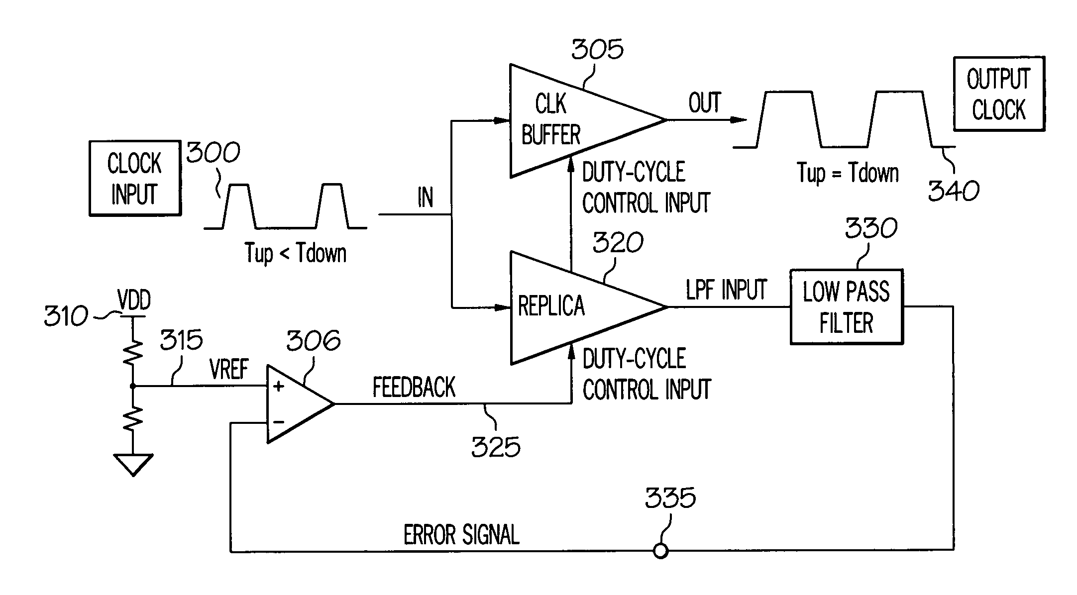
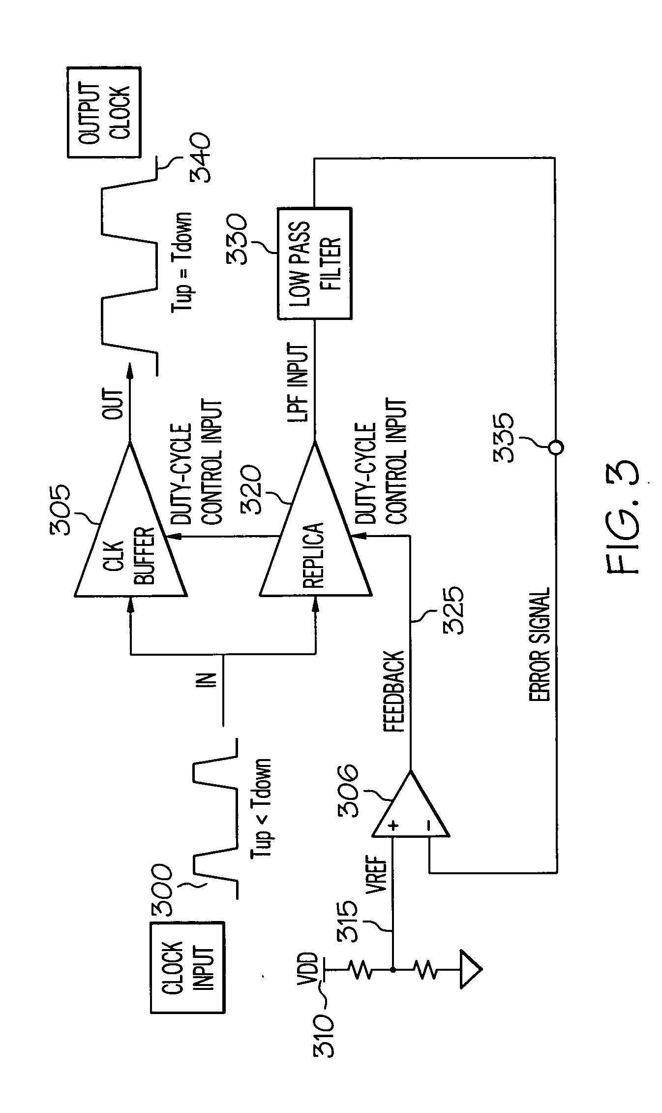
[0021] The present invention provides a circuit design and method for correcting duty-cycle distortions of a differential clock signal propagating through a differential amplifier (or clock buffer). The circuit devices utilized include a differential amplifier, low-pass filter, and correction current source, which are combined into a simple two stage amplifier circuit with a correction output that is dotted to the differential output of a differential buffer.

[0022] A correction circuit is coupled to both (differential) output pulses / signals from the differential amplifier. The correction circuit comprises a differential low pass filter, which filters out the DC (direct current) components of each output pulse / signal of the differential output, and a differential error amplifier, which compares the DC outputs from the low pass filter and generates a pair of differential error-adjustment DC currents. The differential error-adjustment DC currents are then fed back into the respective ...


PUM


Abstract

A completely differential approach to correcting duty-cycle distortions of a differential clock signal propagating through a differential amplifier. A duty-cycle distortion correction (DCDC) differential amplifier circuit/device is provided with a differential amplifier whose output wires are coupled to a correction circuit. The correction circuit comprises a differential low pass filter and a differential correction amplifier. The differential correction amplifier's output is dotted back into the output of the amplifier. The differential output of the amplifier is passed through the low pass filter, which provides differential DC output signals that triggers respective correction amplifier transistors to generate an inverted correction current that is added back to respective differential output pulse. The DCDC differential amplifier provides a completely differential approach to correction of duty-cycle distortions within the differential output.

Description

BACKGROUND OF THE INVENTION [0001] 1. Technical Field [0002] The present invention relates generally to electrical circuit devices and specifically to signal propagation through electrical circuit devices. Still more particularly, the present invention relates to a method and circuit device for correcting duty-cycle distortion in signals propagating through electrical circuit devices. [0003] 2. Description of the Related Art [0004] Duty-cycle in electrical circuit devices is a measure of the up pulse time versus the cycle period time for a clock signal propagating through the device. With many current device implementations, these clock signals are differential clock signals (rather then single ended clock signals), and tend to exhibit distortions in their duty-cycle as they propagate through the device. [0005] Conventional circuit devices, such as ASICs (application-specific integrated circuits), for example, receive and propagate differential clock input signals with an up and dow...

Claims


Application Information

Patent Timeline
IPC IPC(8): H03K3/017
CPCH03K5/1565
Inventor DWARKA, AMARSTEVENS, JOSEPH MARSH
Owner IBM CORP
Why Eureka
Try Eureka