

Electronic endoscope apparatus which superimposes signals on power supply
- Summary
- Abstract
- Description
- Claims
- Application Information
AI Technical Summary
Benefits of technology
Problems solved by technology
Method used
Image

Examples
first embodiment
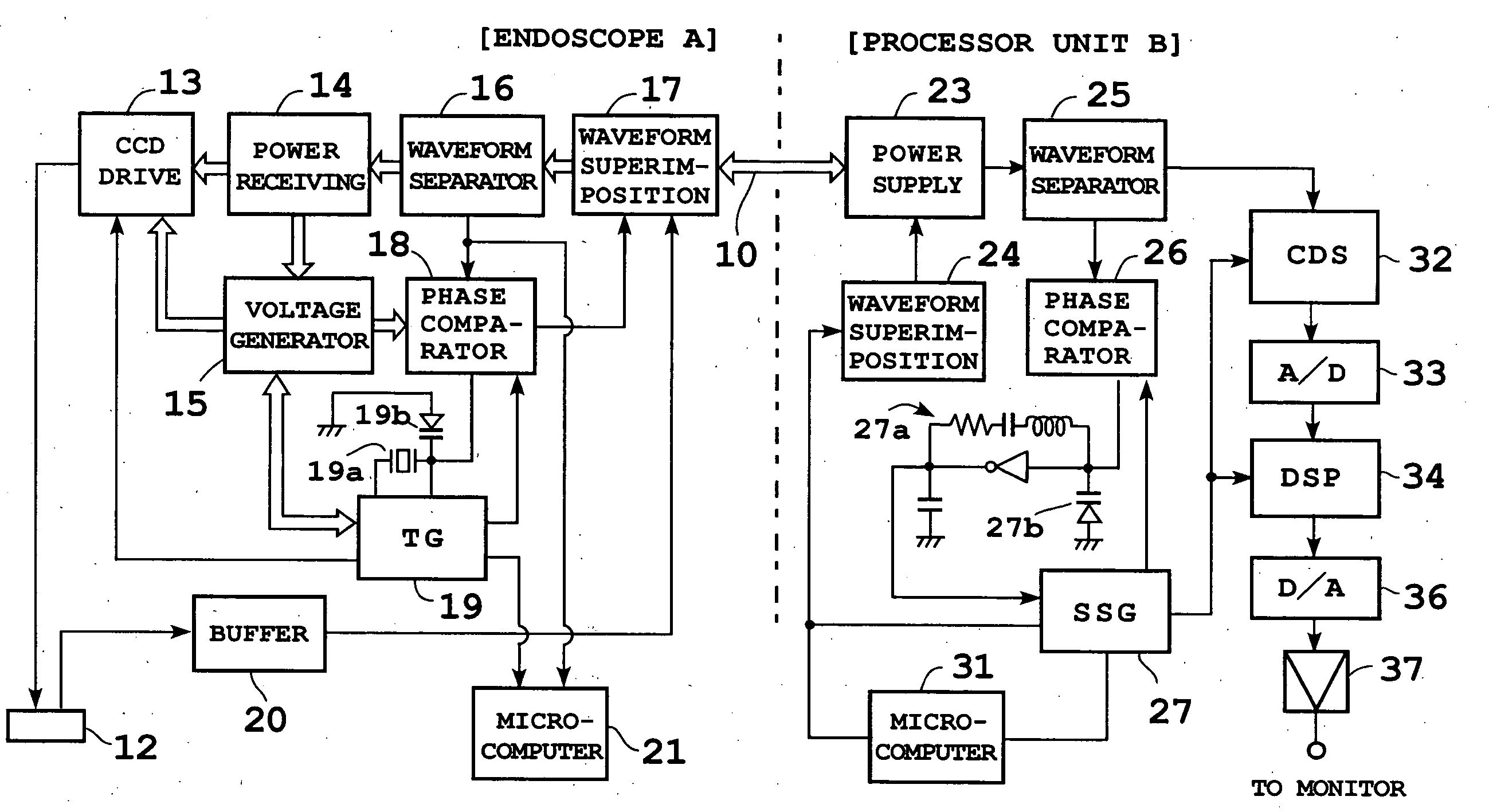
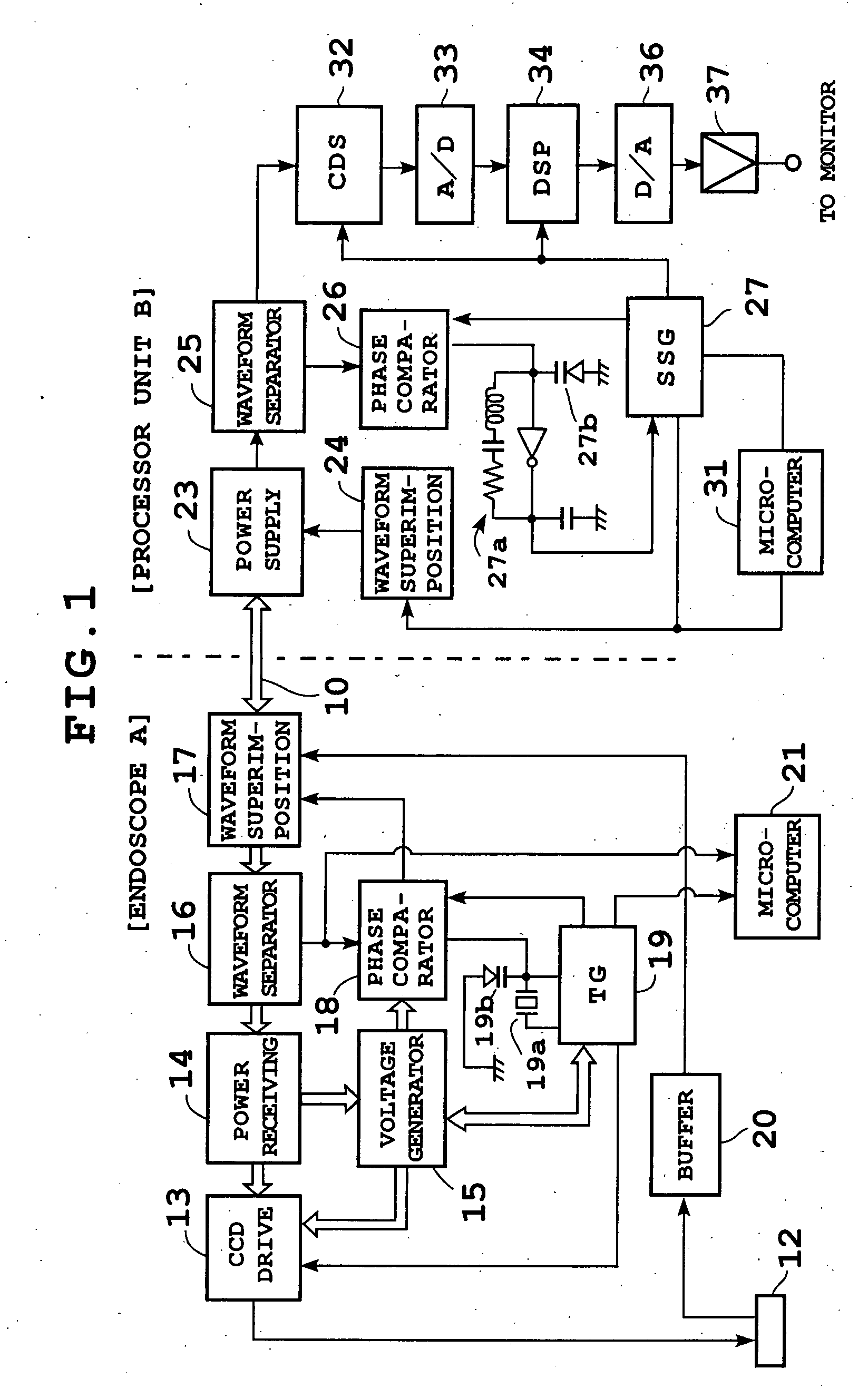
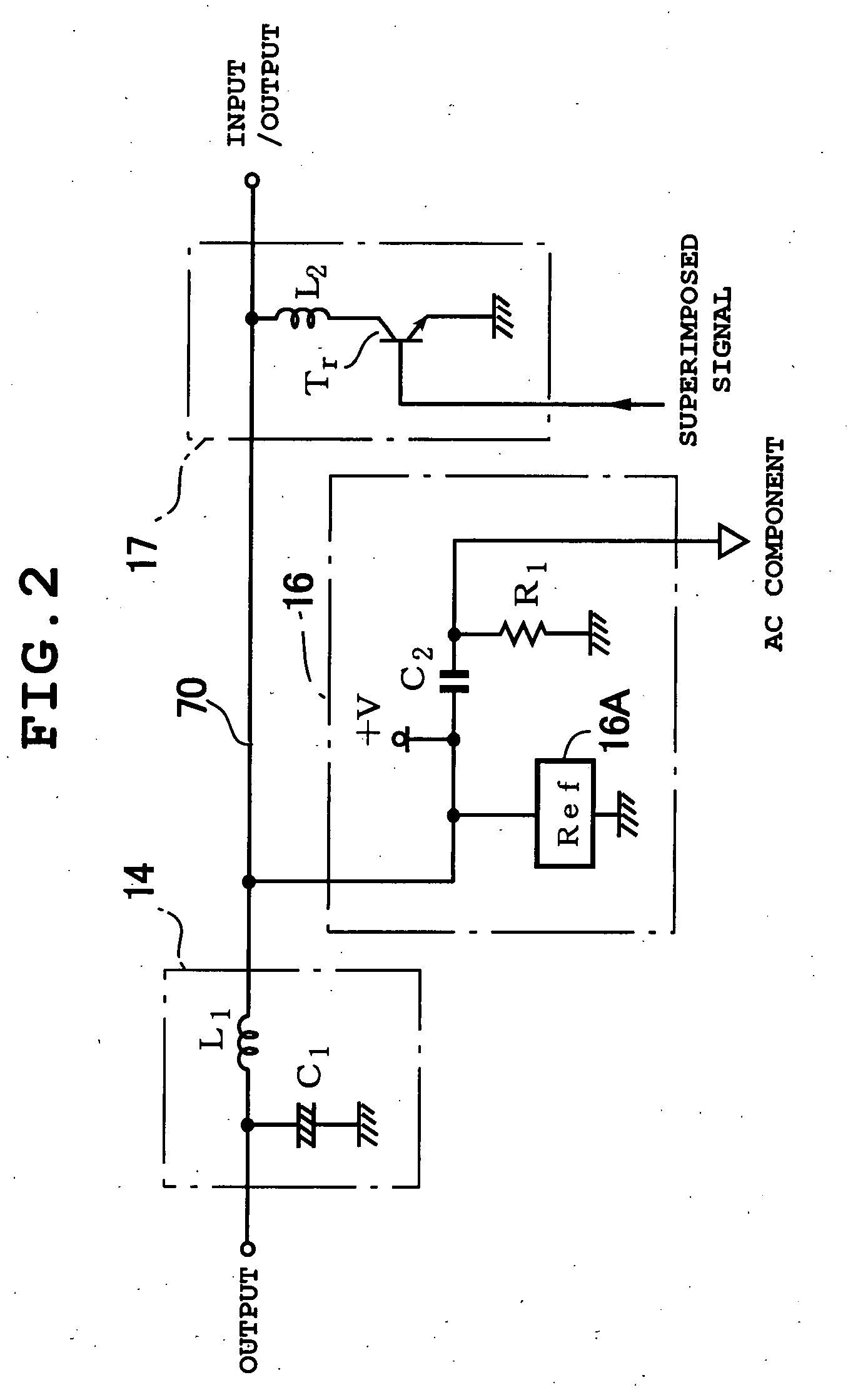
[0040]FIGS. 1 and 2 show configuration of an electronic endoscope apparatus according to a first embodiment. In FIG. 1, a scope A is connected to a processor unit by a single coaxial cable 10 which is a common power / signal line. The tip of the scope A is equipped with, for example, a 270,000-pixel CCD 12 and supplied with an illuminating beam (not shown) from a light source unit via a light guide.
[0041] The scope A comprises a CCD drive circuit 13 which drives the CCD 12, power receiving circuit 14 which feeds DC (direct current) power, switching regulator, etc. Also, it is equipped with a voltage generating circuit 15 which produces a plurality of supply voltages using power transmitted from the power receiving circuit 14; waveform separating circuit 16 which separates control signals and the like superimposed on the power transmitted through the coaxial cable 10; waveform superimposing circuit 17 which superimposes a waveform of a video signal (interlaced scanning) and control si...
second embodiment
[0063]FIG. 5 shows configuration of an electronic endoscope apparatus according to a second embodiment. The basic configuration is similar to that of the first embodiment. The tip of the scope A is equipped with, for example, a 410,000-pixel CCD 112 and an electronic shutter circuit 113. The electronic shutter circuit 113 drives the CCD 112, sets the number of sweep-out pulses (SUB pulses) for sweeping out charge accumulated in the CCD 112, and thereby variably controls charge accumulation time (exposure time) for actual charge accumulation as electronic shutter speed.
[0064] Also, the scope A is equipped with a power receiving circuit 14, voltage generating circuit 15, waveform separating circuit 16, and waveform superimposing circuit 17. The waveform superimposing circuit 17 waveform-superimposes the video signal on transmitted power. Also, it superimposes scope-side reference pulses on the blanking period of the first horizontal line signal in the first field of the video signal,...
third embodiment
[0085]FIG. 10 shows configuration of an electronic endoscope apparatus according to a third embodiment. The third embodiment uses an electromagnetic coupler in a similar configuration with the first embodiment. Specifically, instead of the coaxial cable 10, an electromagnetic coupler 210 is used for electromagnetic coupling. The electromagnetic coupler 210 comprises a primary winding 210a on the side of the processor unit B and a secondary winding 210b on the side of the scope A, placed at a predetermined interval. Alternatively, it is possible to install the electromagnetic coupler 219 in an optical connector connecting the light source unit to the scope A, supply AC power from the light source unit, and transmit the video signal and the like through a signal line connecting the light source unit and processor unit.
[0086] The scope A is equipped with a CCD 212 with a pixel count of 270,000, CCD drive circuit 213, power receiving circuit 214 which converts alternating current (AC) ...
PUM
 Abstract
Description
Claims
Application Information