
Color filter array with neutral elements and color image formation

a color filter array and neutral element technology, applied in the field of electronic photography, can solve the problems that the optimal design of human visual systems is not necessarily 50 % luminance sampling rate, and achieve the effects of reducing light intensity, high spatial resolution, and high sampling rate for luminan

Inactive Publication Date: 2007-07-12
LUO GANG
View PDF15 Cites 32 Cited by
  • Summary
  • Abstract
  • Description
  • Claims
  • Application Information

AI Technical Summary

Benefits of technology

[0008]The present invention is directed to a method and a device for providing higher performances of image capturing and rendering than conventional methods and devices.
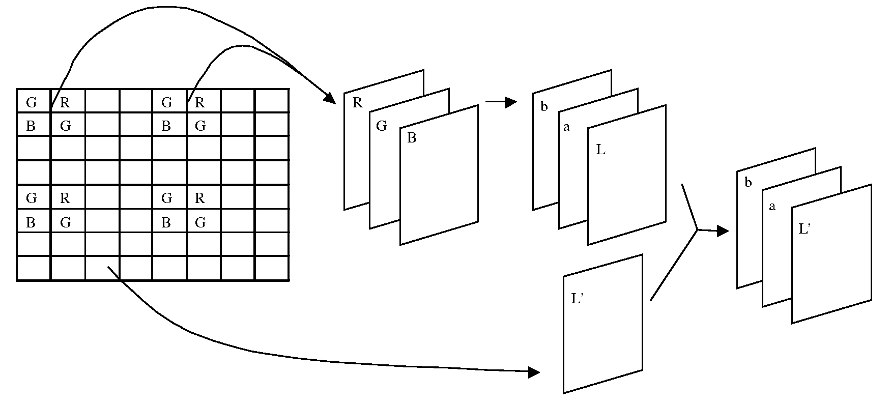
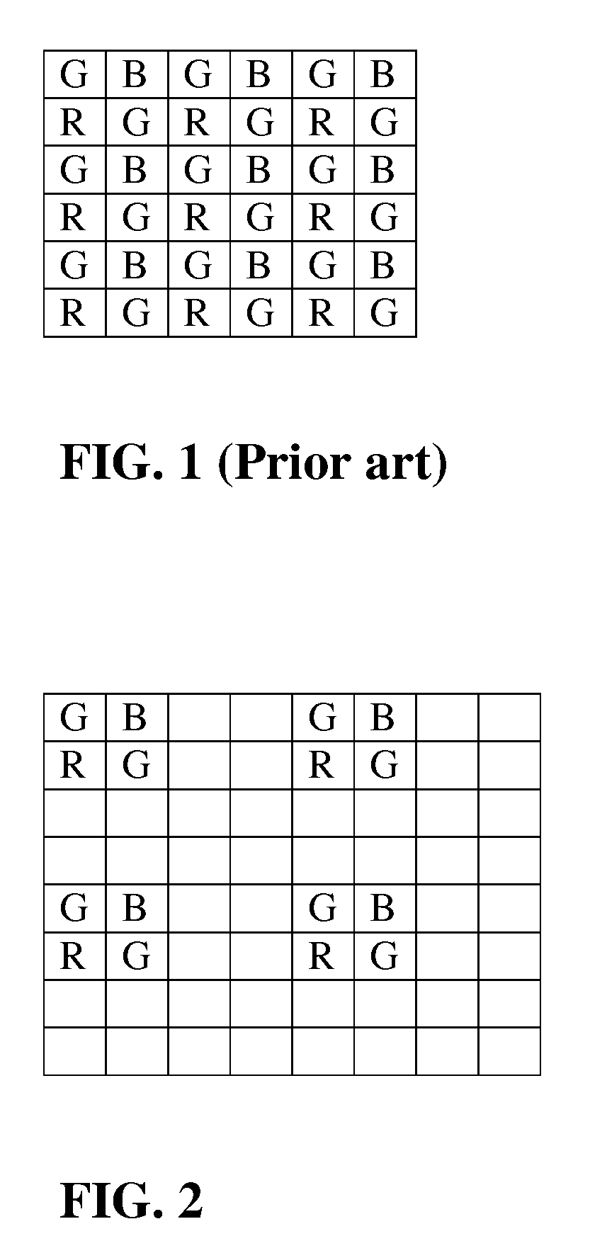
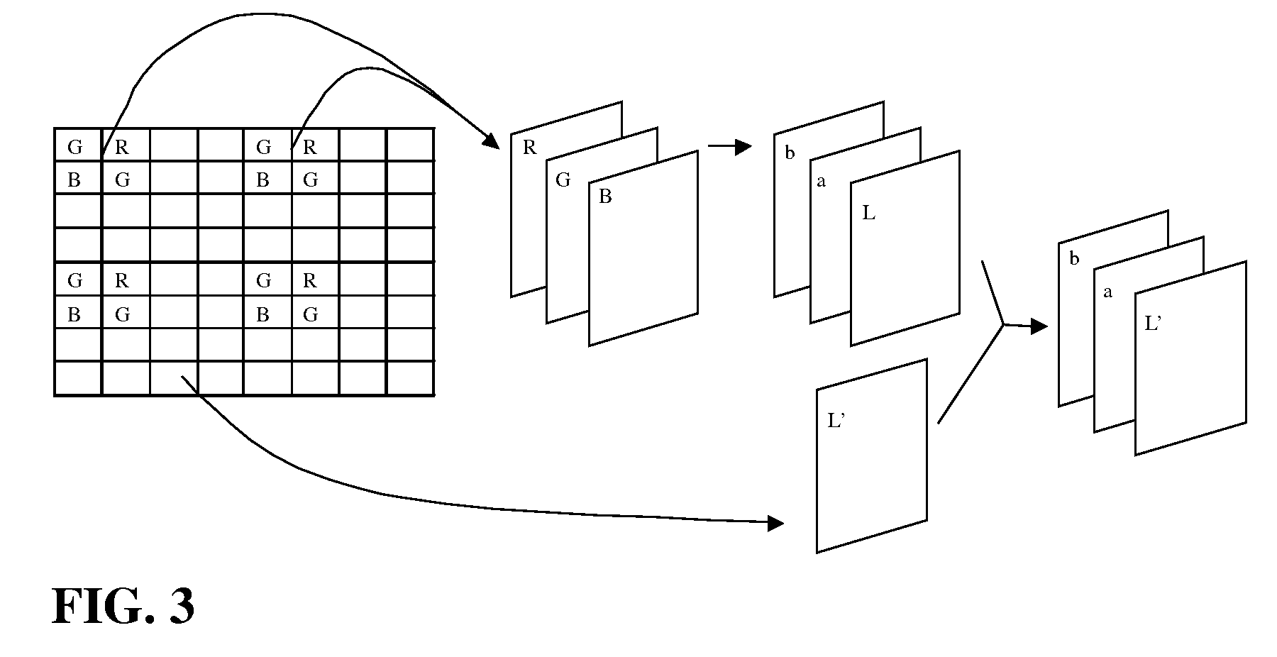
[0009]An object of the present invention is to provide CFA patterns that can achieve higher sampling rate for luminance than for chrominance. A majority of the CFA's are neutral elements without color selectivity. These elements can be neutral density filters, which only reduce the intensity of light, or completely transparent, which do not cause light energy loss. Gray scale images with high spatial resolution and high light sensitivity can be acquired from image samplings at these neutral elements.
[0010]Another object of the invention is to provide CFA patterns that can yield low color artifacts in output images in spite of sparse sampling of chrominance. The remaining elements of the CFA other than neutral elements are color filtered ones. Color elements cluster to form a repeating block pattern, and each block includes several types of color filter elements that are necessary for calculation of at least one color pixel. Color images with low spatial resolution but low color artifacts can be acquired from image samplings at these color filter elements.

Problems solved by technology

However, the 50% sampling rate of luminance is not necessarily the optimal design for a human visual system.

Method used


Image

  • Color filter array with neutral elements and color image formation
  • Color filter array with neutral elements and color image formation
  • Color filter array with neutral elements and color image formation

Examples


Embodiment Construction

[0022]The present invention is a device and method that addresses certain disadvantages of prior art for digital imaging devices that use a color filter array (CFA). FIG. 1 shows the CFA pattern disclosed in U.S. Pat. No. 3,971,065 by Bayer. Unlike devices employing the Bayer pattern, the present invention collects and calculates real luminance and real chrominance information separately. Unlike the inventions disclosed in U.S. Pat. Nos. 5,323,233 and 5,914,749, the present invention is directed to sampling luminance information with a majority (>50%) of image sensor elements, and to sampling chrominance information with a minority of image sensor elements.

[0023]The benefit of providing neutral elements between color elements is several-fold. It enhances the signal to noise ratio that is addressed in Bawolek et al.'s patent (U.S. Pat. No. 5,914,749) and Yamagami, et al.'s patent (U.S. Pat. No. 5,323,233) so that imaging apparatus with high light sensitivity can be made by adopting t...


PUM


Abstract

The invention is directed to a method and a device for providing higher performance imaging capture using a novel pattern of a color filter array that enables one to achieve higher sampling rate for luminance than for chrominance. A majority of the elements in the CFA are neutral elements. Gray scale images with high spatial resolution and high light sensitivity can be acquired from image samplings at these neutral elements. The remaining elements of the CFA are color filtered ones. Color elements cluster to form a repeating block pattern. Color images with low spatial resolution but low color artifacts can be acquired from image samplings at these color filter elements. The color images are transformed into a luminance-chrominance color space, and the luminance components are replaced with the gray scale images to regain high spatial resolution.

Description

CROSS-RELATED APPLICATION[0001]Under 35 U.S.C. 119(e)1), this application claims the benefit of provisional application serial number, 60 / 758,361, filed Jan. 12, 2006, entitled, “Color filter array with neutral elements and color image formation.”FIELD OF INVENTION[0002]The invention relates generally to the field of electronic photography, and in particular to electronic imaging apparatus having a single imaging sensor and a color filter array.BACKGROUND OF INVENTION[0003]A color filter array (CFA) is a required component in single-chip color imaging devices. Its pattern, consisting of color filter elements, allows “color-blind” sensors such as Charge Coupled Devices (CCD), complimentary metal oxide semiconductor (CMOS) and charge-injection device (CID) sensors to capture vivid full-color images. The most commonly adopted CFA pattern is the Bayer pattern as cited in U.S. Pat. No. 3,971,065 and incorporated herein by reference, which consists of 50% of green elements and 25% of elem...

Claims


Application Information

Patent Timeline
IPC IPC(8): H04N9/04
CPCH04N2209/047H04N9/045H04N25/134
Inventor LUO, GANG
Owner LUO GANG
Learn More