Transcleral opthalmic illumination method and system

Inactive Publication Date: 2007-07-12
MEDIBELL MEDICAL VISION TECH
View PDF5 Cites 42 Cited by
  • Summary
  • Abstract
  • Description
  • Claims
  • Application Information

AI Technical Summary

Benefits of technology

[0008] Accordingly, this invention provides a system for transcleral illumination of the eye interior, without touching the eye. Such a system eliminates the chance of damaging the eye or causing discomfort to the patient as has been heretofore. Moreover,

Problems solved by technology

These systems suffer from reflections of the illuminating light off the cornea, crystalline lens, and its interface with the vitreous cavity.
They are thus of limited use for patients with nondilating pupils, such as those with chronic glaucoma, uveitis, and

Method used


Image

  • Transcleral opthalmic illumination method and system
  • Transcleral opthalmic illumination method and system
  • Transcleral opthalmic illumination method and system

Examples


example 1

Illumination Focusing Element Attached to a Chin Rest

[0053]FIG. 5 shows an example of the present invention in conjunction with the imaging optics of a standard fundus camera (by way of example Topcon's TRC-50X) that operates at a distance of approximately 5 cm from the eye cornea. In the camera of FIG. 5, the elements that focus the light on the eye sclera are coupled to a chin rest system that fixes the patient's face and eye position relative to the projected light and with the possibility of directing the orientation of the eye. Optical fiber 11 (see also FIG. 2) conveys the light from the light source to condenser 13, which is supported by the adjustable arm 16 that gives a full freedom to focus the light spot to the right position on the patient's eye sclera as in FIG. 1. Focusing of the spot takes place while the patient's head is resting on the chin rest 17. When illuminating the sclera with condenser 13 (see FIG. 2), the optics of the TRC-50X (by way of example) conveys th...

example 2

Illumination and Focusing Elements Encased in a Device that Positions the Patient's Eye Appropriately for Transcleral Illumination

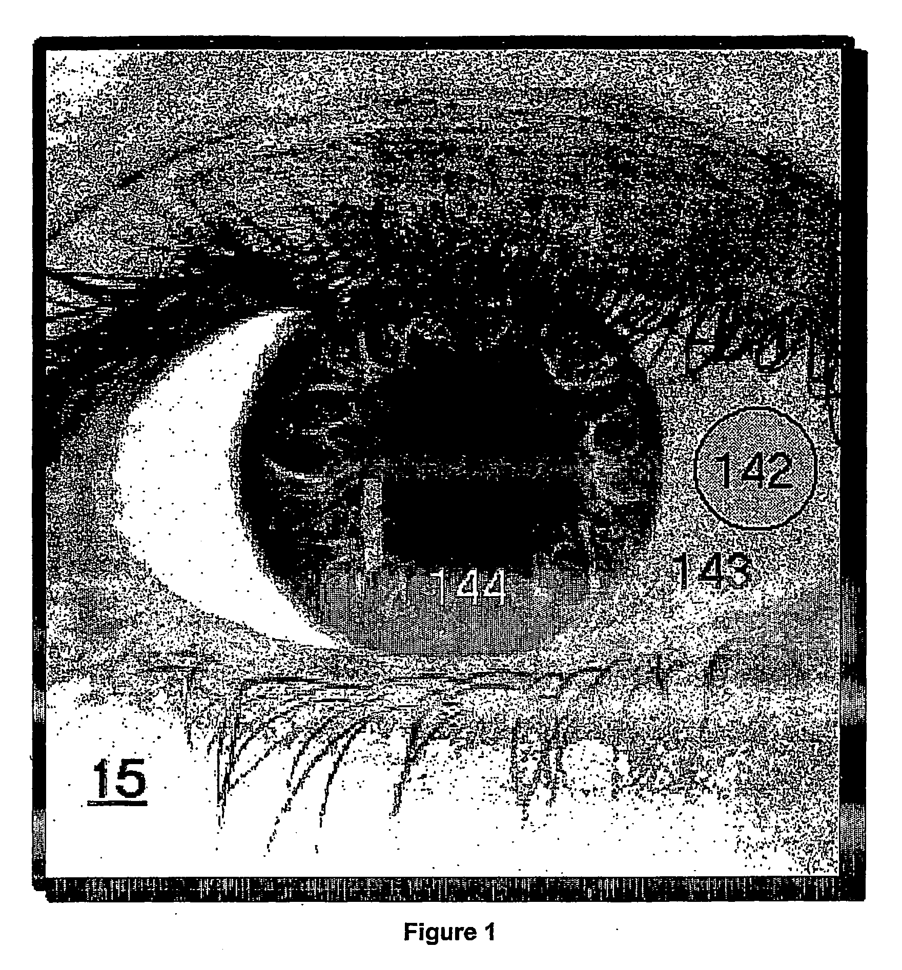
[0056] Further, in yet another embodiment of the invention, optical fiber 11 can be split into two, leading to optics 131 that illuminate the sclera simultaneously both on the nasal and on the temporal sides of the eye. FIGS. 8(a) and 8(b), illustrate a device that encases optics 141 to focus the light illumination spots 142 that originate from optical fiber ends 151 on the sclera of eye 15. Device 131 is coupled to a chin rest, and the two optical fiber ends stem from a single optical fiber (e.g., optical fiber 11 in FIG. 2) that is split into two (see e.g., FIG. 9) by a well-known technology. Head positioning on the chin rest is done in a way that the patient approaches it with the eye first, to touch ring 161 externally to the eyelids, and only afterwards adjusts the chin rest to support the head for the acquisition. The observation and imaging system...

example 3

Illumination Focusing Element Attached to the Same Moving Platform as the Optical Imaging System Apart from Rotation

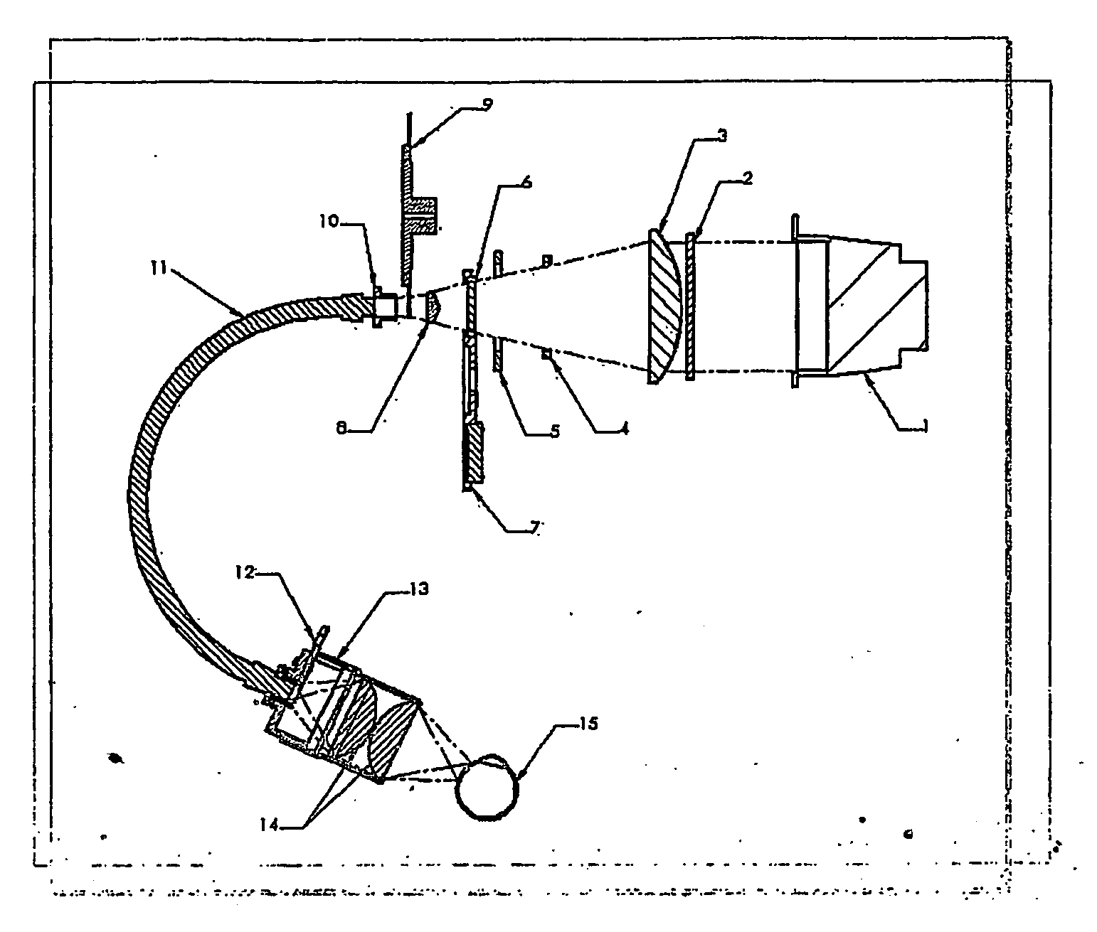
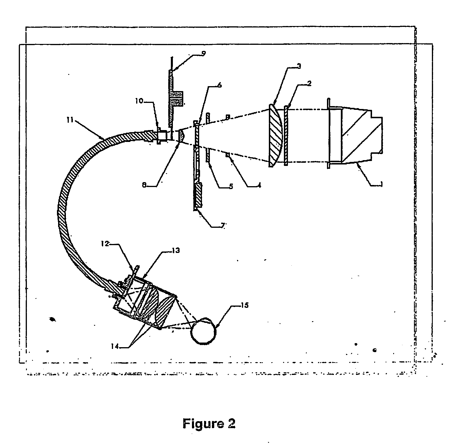
[0060]FIGS. 10 and 11 show a third example of the present invention. In FIG. 10, the present invention is implemented in conjunction with the imaging optics of a standard fundus camera that operates at a distance of approximately 5 cm from the eye cornea. In the system of FIG. 10, the elements that focus the light onto the eye sclera are coupled to the optical system that is used to observe the interior of the eye in a way that whenever the optics is properly positioned to observe the interior of the eye, the illumination light spot is properly focused at the right position on the eye sclera. In FIG. 11, the present invention is implemented with an imaging optics that was especially designed to exploit the advantages of non-contact transcleral illumination. As in the system of FIG. 10, in FIG. 11, the elements that focus the light onto the eye sclera are coupled to th...


PUM


Abstract

A method and apparatus for illuminating the interior of the eye through the sclera without any contact to the eye. The apparatus contains a lamp element and optics that focus the light on the eye sclera. One or more fiber optics bundles may be used to convey the light from the light source close to the illuminated eye, ending with condensing optical elements. Alternatively, light could be conveyed by sharing the optics of an imaging system. It is useful for observing or imaging the interior of the eye, the retina, or the choroid. The observation or the imaging of the interior of the eye, the retina, or the choroid by applying the disclosed illumination method can be done in conjunction with any system that includes optics for that purpose, e.g., fundus cameras and ophthalmoscopes, without using those systems' illumination elements.

Description

BACKGROUND [0001] The present application claims priority from U.S. Provisional Application Ser. No. 60 / 460,821, filed Apr. 8, 2003, and U.S. Provisional Application Ser. No. 60 / 515,421, filed Oct. 30, 2003. The disclosures of both these applications are incorporated by reference herein in their entirety.FIELD [0002] This invention relates to ophthalmoscopes, fundus cameras, slit lamps and operation microscopes, i.e., instruments for viewing and imaging the interior of the eye. More particularly, the invention provides an illumination method serving to provide adequate illumination for diagnostic and documentation purposes of these systems, while making their operation possible without pupil dilation, while enlarging their observable field to the whole fundus, and by-passing illumination difficulties due to opacities and scattering of the anterior chamber of the eye. The observable field is the area of the fundus beyond which the observation system is unable to reach. PRIOR ART [000...

Claims


Application Information

Patent Timeline
IPC IPC(8): A61B3/10A61BA61B3/00A61B18/18
CPCA61B3/0008A61B3/13A61B3/12
Inventor GIL, TAMIRWIGDERSON, ODEDSASSON, AMITNIZANI, ZVI
Owner MEDIBELL MEDICAL VISION TECH
Why Eureka
Try Eureka