Image forming apparatus

Inactive Publication Date: 2007-07-12
KYOCERA DOCUMENT SOLUTIONS INC
View PDF7 Cites 7 Cited by
  • Summary
  • Abstract
  • Description
  • Claims
  • Application Information

AI Technical Summary

Benefits of technology

[0011]An object of the present invention is to further improve image reproducibility in the case

Problems solved by technology

However, since a dark electric potential distribution, an intermediate sensitivity distribution, and a light sensitivity distribution at respective positions in the main scan

Method used


Image

  • Image forming apparatus
  • Image forming apparatus
  • Image forming apparatus

Examples


Embodiment Construction

[0027]Hereinafter, an embodiment of the present invention is described with reference to the attached drawings. It should be noted that the embodiment described herebelow is one example embodying the present invention, and is not the one having a characteristic of limiting a technical scope of the present invention.

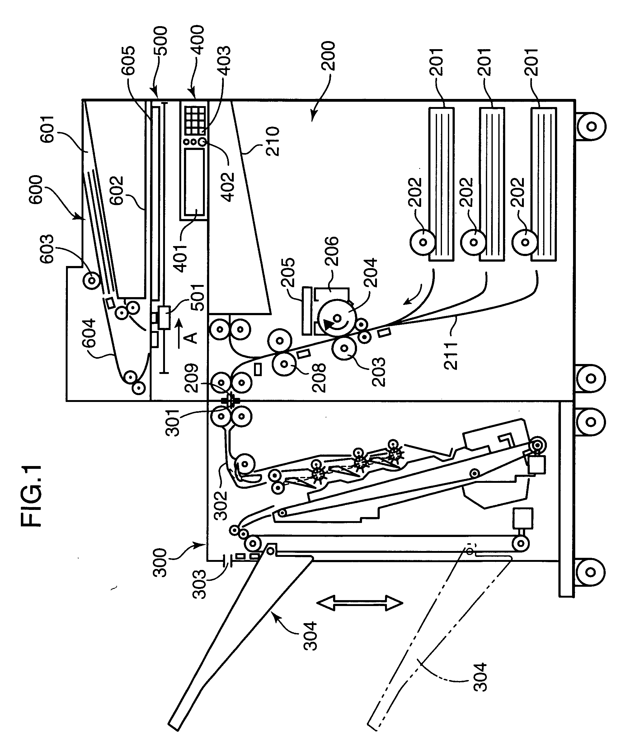
[0028]FIG. 1 is a side schematic diagram mainly showing a mechanical construction of an image forming apparatus according to the embodiment of the present invention. The image forming apparatus includes a main body 200, a sheet post processing section 300 provided in a left side of the main body 200, an operating section 400 for allowing a user to input various operating instructions and the like, a document reading section 500 provided in an upper portion of the main body 200, and a document feeding section 600 provided on an upper portion of the document reading section 500.

[0029]The operating section 400 includes a display panel 401, a start key 402, numerical keys 403...


PUM


Abstract

An input dither pattern determiner divides an input dither image to plural blocks, and determines an input dither pattern for each block. An output dither image portion converts the input dither pattern for each block to an output dither pattern. A reference emission time determiner portion determines a reference emission time for each block based on dark electric potential distribution and intermediate sensitivity distribution of a photoconductive drum, a light intensity distribution of a laser beam in a main scanning direction, and the output dither pattern. An area emission time calculator determines area emission time for each area based on a reference emission time for each block. An actual emission time calculator adjusts emission time for each area so that differences between reference emission times of blocks adjacent one another in the main scanning direction become a predetermined value or lower, and calculates actual emission time for each area.

Description

BACKGROUND OF THE INVENTION[0001]1. Field of the Invention[0002]The present invention relates to an image forming apparatus such as a network printer, a digital composite machine, a copying machine and a facsimile apparatus.[0003]2. Description of the Related Art[0004]U.S. Pat. No. 5,134,495 discloses a pseudo high resolution technique. According to this technique, for example, even in the case where an original image having a resolution of 1200 dpi is to be formed by a printer having a reproducible resolution of 600 dpi, the printer simulatedly reproduces a 1200 dpi image by adjusting an emission time of a laser beam for each pixel.[0005]FIG. 12 is a diagram for describing the technique disclosed in the U.S. Pat. No. 5,134,495. The technique disclosed in the U.S. Pat. No. 5,134,495 is described in accordance with FIG. 12. At first, an original image transmitted from a device such as a personal computer is converted to an input dither image by a known dither method. The input dither...

Claims


Application Information

Patent Timeline
IPC IPC(8): G06F15/00
CPCH04N1/40037
Inventor NAKANO, ISSEINAKAI, JUN
Owner KYOCERA DOCUMENT SOLUTIONS INC
Why Eureka
Try Eureka