Nonvolatile semiconductor memory device
- Summary
- Abstract
- Description
- Claims
- Application Information
AI Technical Summary
Benefits of technology
Problems solved by technology
Method used
Image
Examples
second embodiment
[0206]FIG. 20 schematically shows a construction of a main portion of the nonvolatile semiconductor memory device according to a second embodiment of the invention. The nonvolatile semiconductor memory device shown in FIG. 20 differs in the following points from the nonvolatile semiconductor memory device shown in FIG. 12. Specifically, in write drive circuit WRD, NAND gates NGA-NGD are further supplied with source line activating signal SLE. Source line drivers SDV are arranged on the opposite sides of each of source lines SL (SL0 and SL1). Specifically, for memory array MA0, there are provided source line drivers SDV01 and SDV0u arranged on the opposite sides of source line SL0, respectively, and for memory array MA1, there are provided source line drivers SDV11 and SDV1u arranged on the opposite sides of source line SL1, respectively. Other constructions of the nonvolatile semiconductor memory device shown in FIG. 20 are the same as those of the nonvolatile semiconductor memory d...
third embodiment
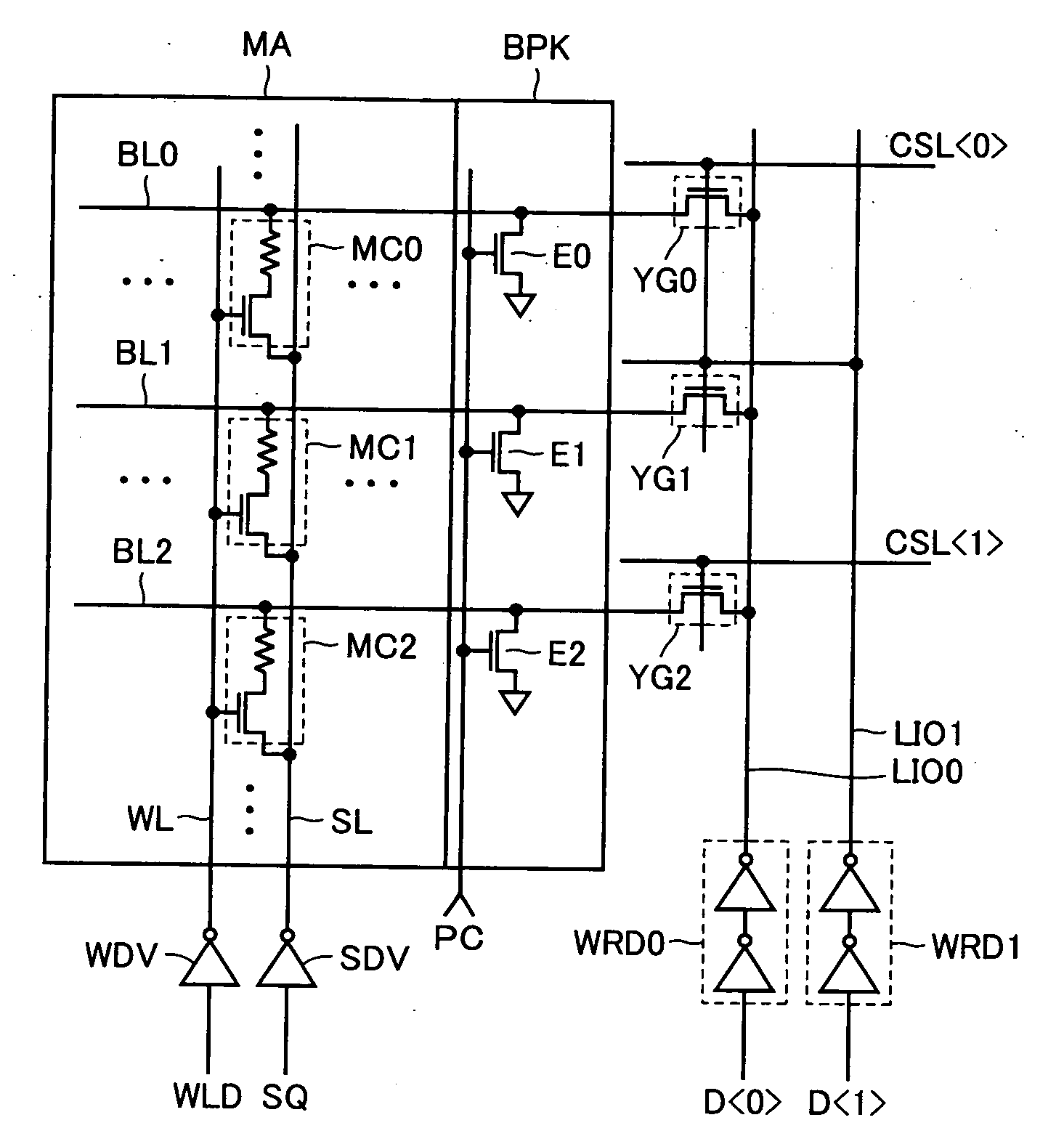
[0240]FIG. 24 schematically shows a construction of a main portion of a nonvolatile semiconductor memory device according to a third embodiment of the invention. FIG. 24 shows a construction for writing and reading the data for one memory array MA.
[0241]The construction shown in FIG. 24 differs from the construction of the memory array shown in FIG. 4 in the following points. Source line drivers SDV0 and SDV1 are aligned to each other in a word line extending direction. Each source line is arranged corresponding to the bit lines in two columns equal in number to the bit width of write / read unit of the data. In FIG. 24, source lines SL and SL are arranged. Each of source lines SL and SL includes a main line portion MSL arranged parallel to bit line BL in the column direction (bit line extending direction), and feeder line portions SSL each arranged for the columns equal in number to the bit width of read / write data and parallel to word line WL and connected to main line portion MSL.
[...
fourth embodiment
[0251]FIG. 25 schematically shows a planar layout of the memory cells in the nonvolatile semiconductor memory device according to the fourth embodiment of the invention. In FIG. 25, active regions AR each for forming two memory cells are aligned in the row direction (word line extension direction) and the column direction (bit line extension direction). Each active region AR has a rectangular form elongated in the column direction, and is isolated by an isolation region (not shown) from others in the row and column directions.
[0252]Source lines SL1 and SL2 are arranged, in the row direction, crossing active regions AR. Source line contacts SCN electrically connect these source lines SL1 and SL2 to impurity regions in active regions AR, respectively. Word lines are arranged on both sides of each of source lines SL1 and SL2. Specifically, word lines WL0 and WL1 are arranged on both sides of source line SL1, respectively, and word lines WL2 and WL3 are arranged on both sides of source ...
PUM
 Abstract
Description
Claims
Application Information
 - R&D
- Intellectual Property
- Life Sciences
- Materials
- Tech Scout
- Unparalleled Data Quality
- Higher Quality Content
- 60% Fewer Hallucinations
Browse by: Latest US Patents, China's latest patents, Technical Efficacy Thesaurus, Application Domain, Technology Topic, Popular Technical Reports.
© 2025 PatSnap. All rights reserved.Legal|Privacy policy|Modern Slavery Act Transparency Statement|Sitemap|About US| Contact US: help@patsnap.com


