
Cutting blade with replaceable cutting cartridge

a cutting blade and cutting blade technology, applied in metal working apparatus, agriculture tools and machines, agriculture, etc., can solve the problems of severing the blade of grass, affecting the cutting effect, dull cutting edge of the blade, etc., and achieve the effect of simple and cost-effectiv

Inactive Publication Date: 2007-07-19
KENNY MARK
View PDF3 Cites 8 Cited by
  • Summary
  • Abstract
  • Description
  • Claims
  • Application Information

AI Technical Summary

Benefits of technology

"The invention provides a cost-effective and simple solution for maintaining a sharp blade edge in a cutting tool. It also provides a secure and safe method for easily replacing a worn-out cartridge with a new one, ensuring continued use of the cutting tool. The invention includes a cutting blade with a replaceable cartridge having a main blade body and a receiving section, a replaceable cartridge with a sharpened edge, and a locking mechanism. The technical effects of the invention include improved durability and flexibility in maintaining a sharp blade edge and increased safety in replacing worn-out cartridges."

Problems solved by technology

The cutting edge of the blades typically become dull very quickly, from constant use and from contact with obstructions.
While the equipment appears to be cutting for a long period of time, in actuality, the cutting edge may have ceased to be a true cutting edge and may thus sever blades of grass only because the mower blade is rotating very fast.
Thus, the blades of grass are broken by the spinning blade and are bruised in the process.
The grass develops a brown tip because of the bruising, has an unpleasing appearance, and is a damaged plant.
Furthermore, since the dull blade must break the grass blades, instead of cutting them, the motor which rotates the blade is under an increased load, thus requiring more maintenance and consuming more fuel.
This procedure is very difficult and very time consuming.
Moreover, the ground or filed blades are often asymmetric and this asymmetry can cause additional torsional forces on the rotating shaft driving the blade, leading to even more costly repairs to the driving motor.
Such replaceable blades have presented problems of one type or another with regard to the requirement of complex fabrications, strength of the replaceable cutter, weakened resistant to damage by foreign objects, costs, and the like.

Method used


Image

  • Cutting blade with replaceable cutting cartridge
  • Cutting blade with replaceable cutting cartridge
  • Cutting blade with replaceable cutting cartridge

Examples


Embodiment Construction

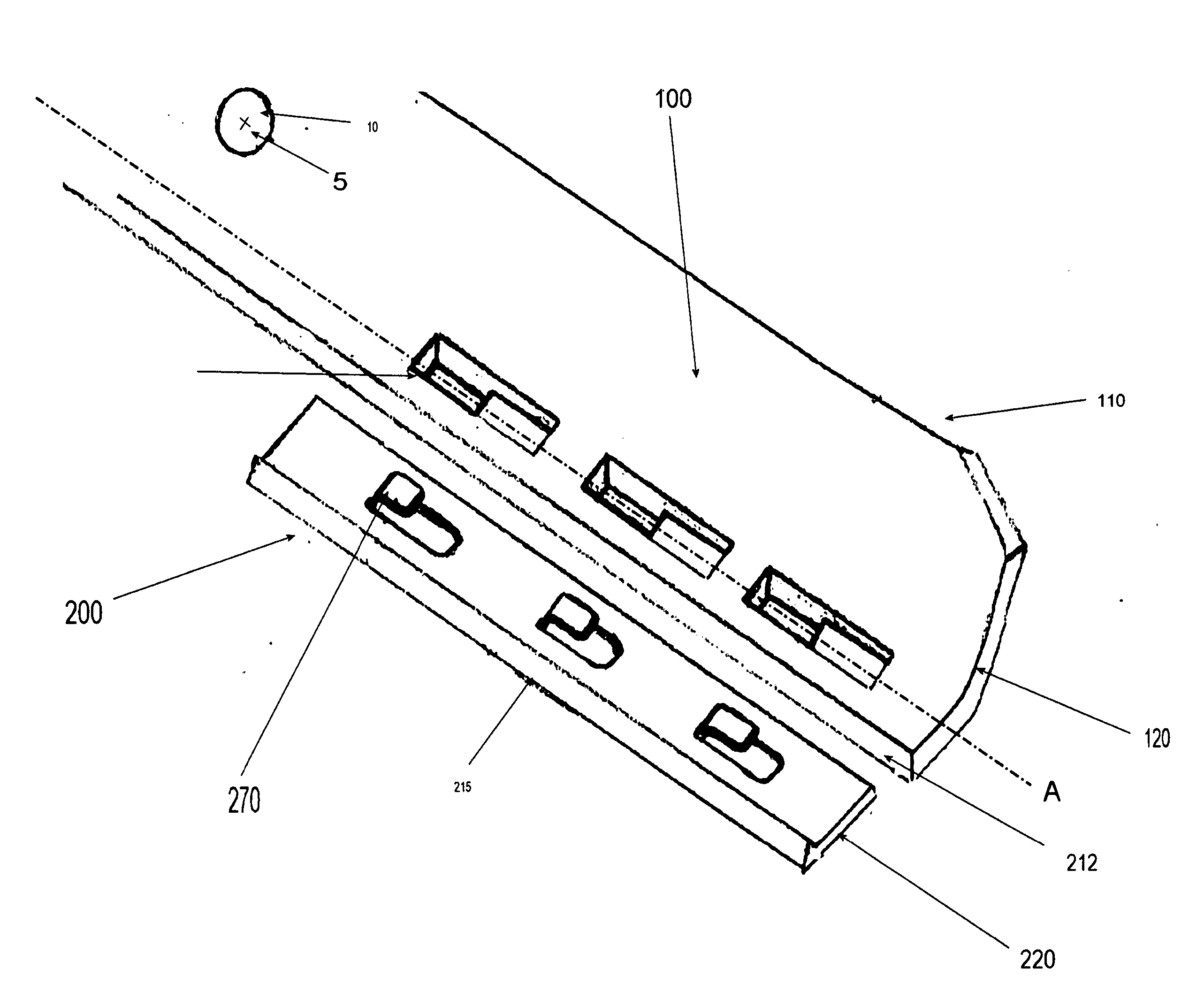
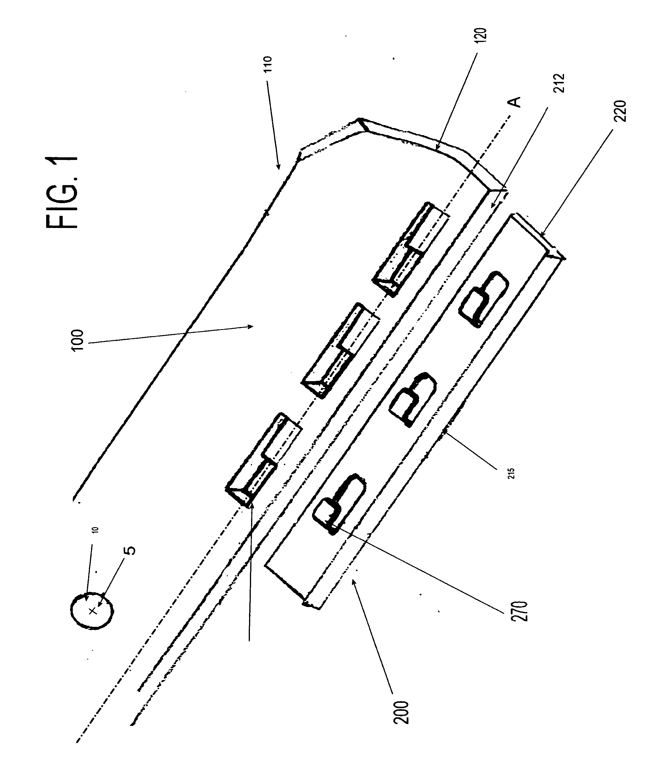
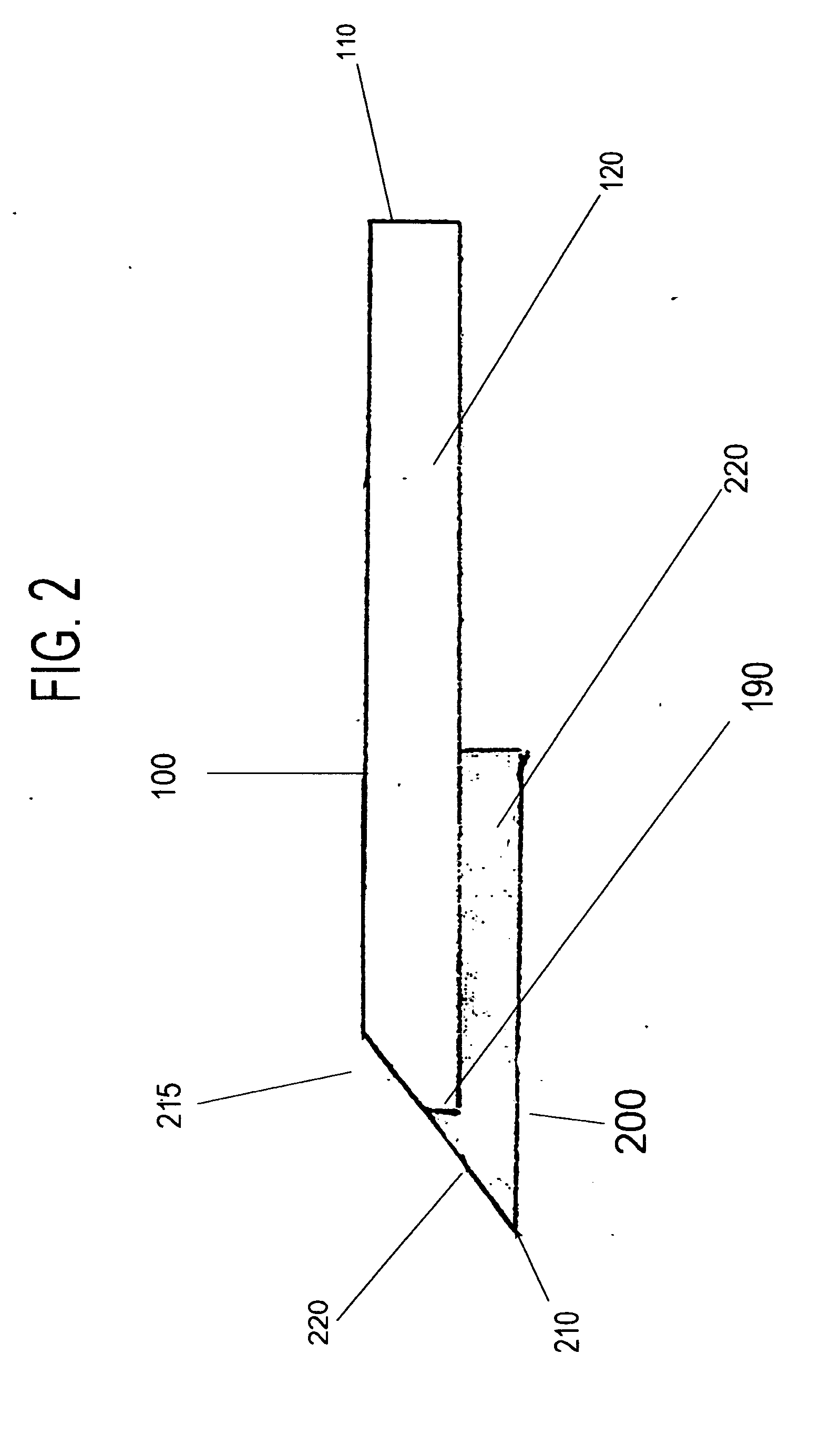
[0018]FIG. 1 shows an exploded view of an exemplary embodiment of the instant invention. The instant invention is directed to a cutting blade having a replaceable cutting edge, the cutting edge being located on a replaceable blade cartridge. The blade comprises, in an exemplary embodiment, a main blade body 100 having a center axis 5 and a mounting hole 10 for mounting to a cutting device. The blade body has a trailing edge 110 and an outside edge 120. Within the main blade body 100 there are receiving sections 150. These sections receive the cartridge, as further explained below. The main blade body 100 also has a main blade body cutting edge 215 (as seen best in FIG. 2). The replaceable cartridge body 200 has a corresponding cartridge outside edge 220, cartridge tabs 270, and a cartridge cutting edge 205.

[0019] In assembling the blade, the replaceable cartridge 200 is brought to the underside of the main blade body 100. The cartridge tabs 270 are lined up with the receiving secti...


PUM


Abstract

The invention includes a cutting blade with replaceable cartridge having a main blade body with an at least one central axis, an at least one receiving section on the main blade body and penetrating through the main blade body. A replaceable cartridge has an at least one sharpened edge thereon and an at least one cartridge tab extending therefrom, the at least one cartridge tabs mating and penetrating and coupling with the at least one receiving section. And a locking mechanism is engaged when the replaceable cartridge is brought into proximity with the main blade body and the at least one receiving section is penetrated and coupled by the at least one cartridge tab.

Description

CROSS-REFERENCE TO RELATED APPLICATIONS [0001] This application claims the priority of U.S. provisional patent application 60 / 732,719, filed Nov. 3, 2005, which is incorporated herein by reference.BACKGROUND OF THE INVENTION [0002] 1. Field of the Invention [0003] The invention relates to a rotary cutting blade with replaceable cutting edge cartridge. [0004] 2. Background of the Invention [0005] Cutting blade systems and rotary cutting blades in particular depend on maintaining an efficient cutting surface to operate effectively. This is especially the case in the professional lawn care industry, where rotary lawn mowers, rotary edgers, and similar devices are typically operated for long hours and over assorted terrain to manicure lawns. The blades of such lawn equipment are generally flat elongated piece of steel which are rotationally symmetric on a rotatable shaft. The blades have a sharpened edge on the leading edge of the outer portion of the blade. The outer portion trailing e...

Claims


Application Information

Patent Timeline
Patent Type & Authority Applications(United States)
IPC IPC(8): B26B3/00
CPCA01D34/73
Inventor KENNY, MARK
Owner KENNY MARK
Learn More