Flexible directional drilling apparatus and method

a directional drilling and flexible technology, applied in directional drilling, drilling pipes, cutting machines, etc., can solve the problems of borehole deviation, high lateral load on the bit, and borehole not maintaining a vertical trajectory along its entire depth,

Inactive Publication Date: 2007-07-19
SMITH INT INC
View PDF45 Cites 105 Cited by
  • Summary
  • Abstract
  • Description
  • Claims
  • Application Information

AI Technical Summary

Benefits of technology

[0016] According to another aspect of the invention, a method of drilling a borehole includes disposing a drill bit and a stabilizer assembly at a distal end of a drillstring, disposing a flex member between a drilling assembly and the stabilizer assembly, drilling the borehole with the drill bit and the drilling assembly, and stabilizing the drill bit with stabilizer pads of the stabilizer assembly.

Problems solved by technology

While most drilling operations begin as vertical drilling operations, often the borehole drilled does not maintain a vertical trajectory along its entire depth.
However, over distances of over several thousand feet, borehole deviation can be significant.
One drawback of directional drilling with a mud motor and a bent housing is that the bend may create high lateral loads on the bit, particularly when the system is either kicking off (that is, initiating a directional change) from straight hole, or when it is being rotated in straight hole.
The high lateral loads can cause excessive bit wear and a rough wellbore wall surface.
Another drawback of directional drilling with a mud motor and a bent housing arises when the drillstring rotation is stopped and forward progress of the BHA continues with the positive displacement mud motor.
During these periods, the drillstring slides further into the borehole as it is drilled and does not enjoy the benefit of rotation to prevent it from sticking in the formation.
Particularly, such operations carry an increased risk that the drillstring will become stuck in the borehole and will require a costly fishing operation to retrieve the drillstring and BHA.
Once the drillstring and BHA is fished out, the apparatus is again run into the borehole where sticking may again become a problem if the borehole is to be deviated again and the drillstring rotation stopped.
Furthermore, another drawback to drilling without rotation is that the effective coefficient of friction is higher, making it more difficult to advance the drillstring into the wellbore.
This results in a lower rate of penetration than when rotating, and can reduce the overall “reach”, or extent to which the wellbore can be drilled horizontally from the drill rig.
The undersized pilot hole is undesirable in the sense that if casing is to be set in the wellbore following the use of such a BHA, the casing must be set at least one hundred feet off bottom.
The remaining uncased hole can be a source of unwanted influx of reservoir fluids or high pressure gas.
However, the high side loads caused by bent-sub directional BHA's could prevent underreamers from opening, or could overload the mechanisms which cause them to expand.

Method used


Image

  • Flexible directional drilling apparatus and method
  • Flexible directional drilling apparatus and method
  • Flexible directional drilling apparatus and method

Examples


first embodiment

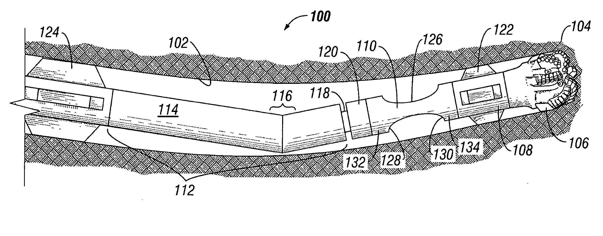
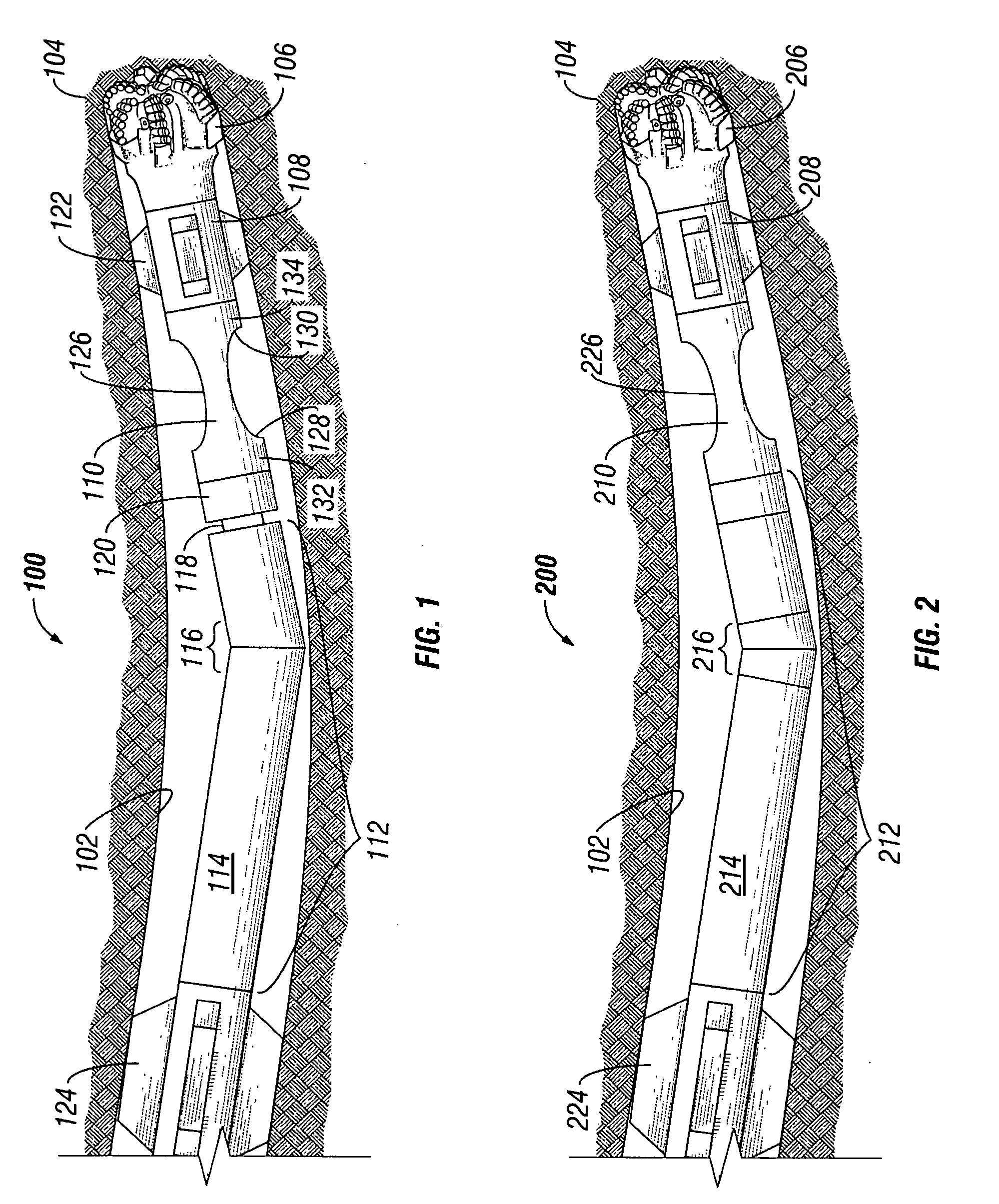
[0037] Referring now to FIG. 1, a bottom hole assembly 100 in accordance with the present invention is schematically shown drilling a borehole 102 in a subterranean formation 104. Bottom hole assembly 100 includes a drill bit 106, a stabilizer assembly 108, a flex member 110, and a drilling assembly 112. Drilling assembly 112, preferably includes a drive mechanism 114 and a directional mechanism 116. In the embodiment shown in FIG. 1, drive mechanism 114 includes a positive displacement mud motor and directional mechanism 116 includes a bent housing assembly integral to the mud motor. As such, an output shaft 118 of positive displacement mud motor 114 extends below bent housing 116 and provides a rotary threaded connection 120 to lower components of BHA 100. Output shaft 118 is powered by the positive displacement mud motor, and therefore rotates relative to the external housing of drive mechanism 114. While drill bit 106 is shown schematically as a polycrystalline diamond compact d...

second embodiment

[0041] Referring now to FIG. 2, a bottom hole assembly 200 in accordance with the present invention is schematically shown drilling a borehole 102 in a subterranean formation 104. Bottom hole assembly 200 includes a drill bit 206, a stabilizer assembly 208, a flex member 210, and a drilling assembly 212. Drilling assembly 212, preferably includes a drive mechanism 214 and a directional mechanism 216. In the embodiment shown in FIG. 2, drive mechanism 214 is a drillstring rotated from the surface and directional mechanism 216 includes an articulated joint of a point-the-bit rotary steerable system. The output housing or shaft of the directional mechanism rotates at the same speed as that of the drive mechanism. As such, flex member 210, similarly to flex member 110 of FIG. 1, includes a reduced outer diameter portion 226 that reduces the magnitude of side loads and stresses experienced by articulated RSS joint 216. In bottom hole assembly 200, drive mechanism 214 may be a turbine or ...

third embodiment

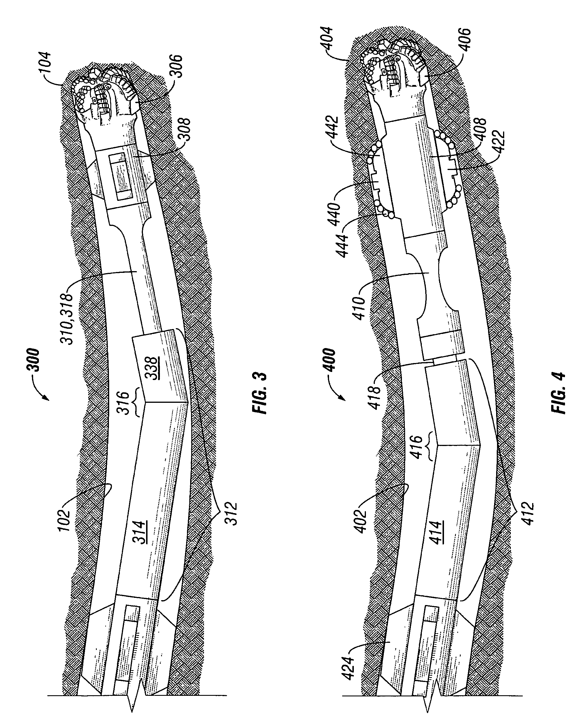
[0042] Referring now to FIG. 3, a bottom hole assembly 300 in accordance with the present invention is schematically shown drilling a borehole 102 in a subterranean formation 104. Bottom hole assembly 300 includes a drill bit 306, a stabilizer assembly 308, a flex member 310, and a drilling assembly 312. Drilling assembly 312, preferably includes a drive mechanism 314 and a directional mechanism 316. In the embodiment shown in FIG. 3, drive mechanism 314 includes a positive displacement mud motor and directional mechanism 316 includes a bent housing. Bottom hole assembly 300 of FIG. 3 differs from bottom hole assembly 100 of FIG. 1 in that flex member 310 is integrated into what would have been an output shaft (e.g. 118 of FIG. 1) of positive displacement mud motor 314. While flex member 110 of FIG. 1 is capable of being retrofitted to any drilling assembly, flex member 310 is specifically designed, tailored, and optimized for a particular drilling assembly 312. Therefore, drilling ...


PUM


Abstract

A bottom hole assembly to directionally drill a subterranean formation includes a drill bit, a stabilizer assembly located proximate to and behind the drill bit, a drilling assembly comprising a drive mechanism and a directional mechanism, and a flex member. Optionally, the flex member may be located between the drilling assembly and the stabilizer assembly or an integral to a housing of the drilling assembly. A method to drill a formation includes positioning a stabilizer assembly behind a drill bit and positioning a flex member between an output shaft of a drilling assembly and the stabilizer assembly. The method preferably includes rotating the drill bit, stabilizer assembly, and flex member with a drilling assembly and directing the trajectory of the drill bit and stabilizer assembly with a directional mechanism of the drilling assembly.

Description

BACKGROUND OF INVENTION [0001] Subterranean drilling operations are often performed to locate (exploration) or to retrieve (production) subterranean hydrocarbon deposits. Most of these operations include an offshore or land-based drilling rig to drive a plurality of interconnected drill pipes known as a drillstring. Large motors at the surface of the drilling rig apply torque and rotation to the drillstring, and the weight of the drillstring components provides downward axial force. At the distal end of the drillstring, a collection of drilling equipment known to one of ordinary skill in the art as a bottom hole assembly (“BHA”), is mounted. Typically, the BHA may include one or more of a drill bit, a drill collar, a stabilizer, a reamer, a mud motor, a rotary steering tool, measurement-while-drilling sensors, and any other device useful in subterranean drilling. [0002] While most drilling operations begin as vertical drilling operations, often the borehole drilled does not maintain...

Claims


Application Information

Patent Timeline
Patent Type & Authority Applications(United States)
IPC IPC(8): E21B7/04
CPCE21B17/20E21B7/04E21B7/06E21B7/067E21B7/068E21B10/26E21B10/32
Inventor UNDERWOOD, LANCE D.DEWEY, CHARLES H.
Owner SMITH INT INC
Why Eureka
Try Eureka