
Automated roofing material removal machine and method

a roofing material and automatic technology, applied in the field of automatic roofing material removal machines and methods, can solve the problems of laborious and often unsafe use of tools, difficult for roofers to adequately and safely manipulate hand held shingle removal tools to remove old shingles and roofing nails or other fasteners,

Active Publication Date: 2007-07-19
ARREL TECH
View PDF12 Cites 11 Cited by
  • Summary
  • Abstract
  • Description
  • Claims
  • Application Information

AI Technical Summary

Benefits of technology

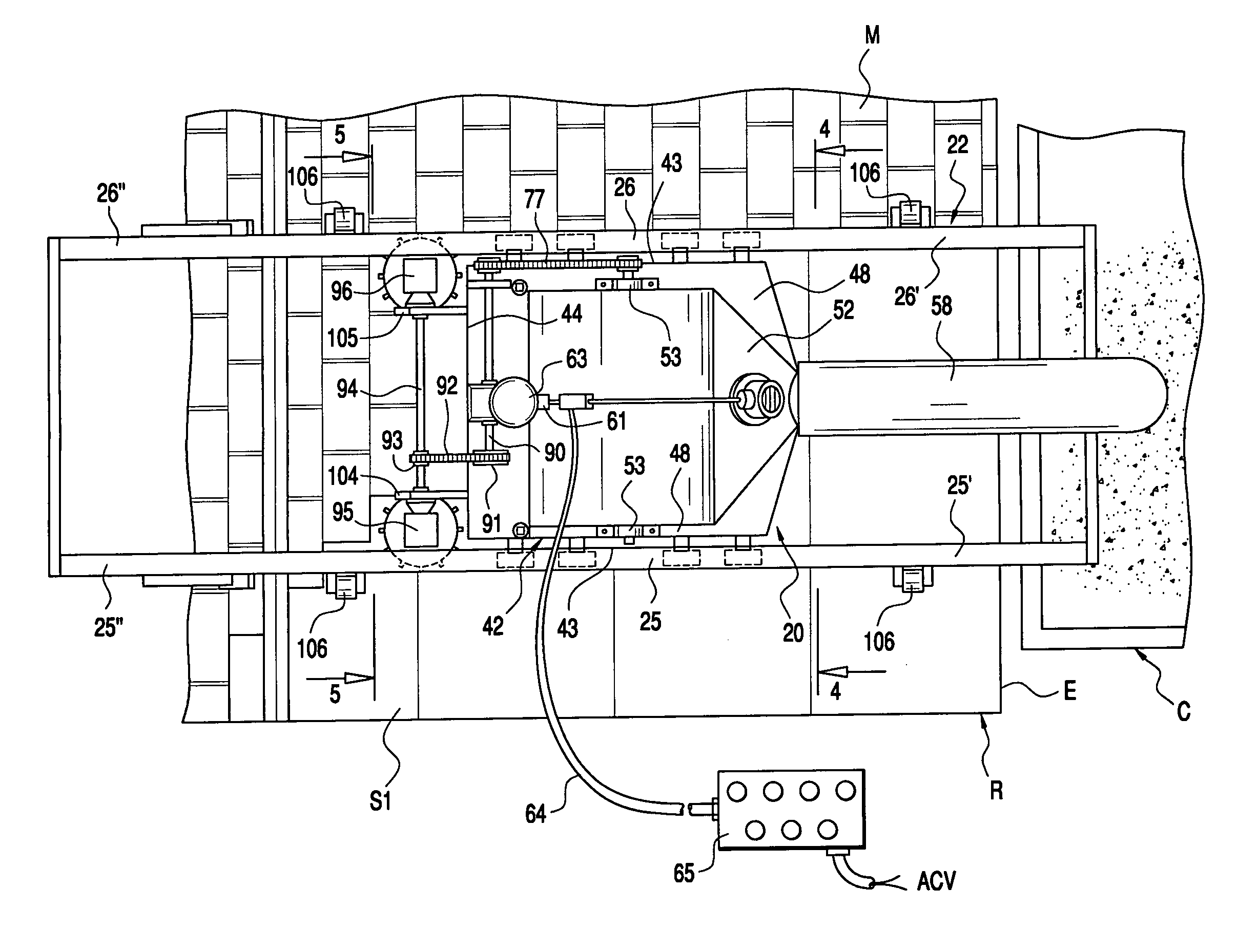
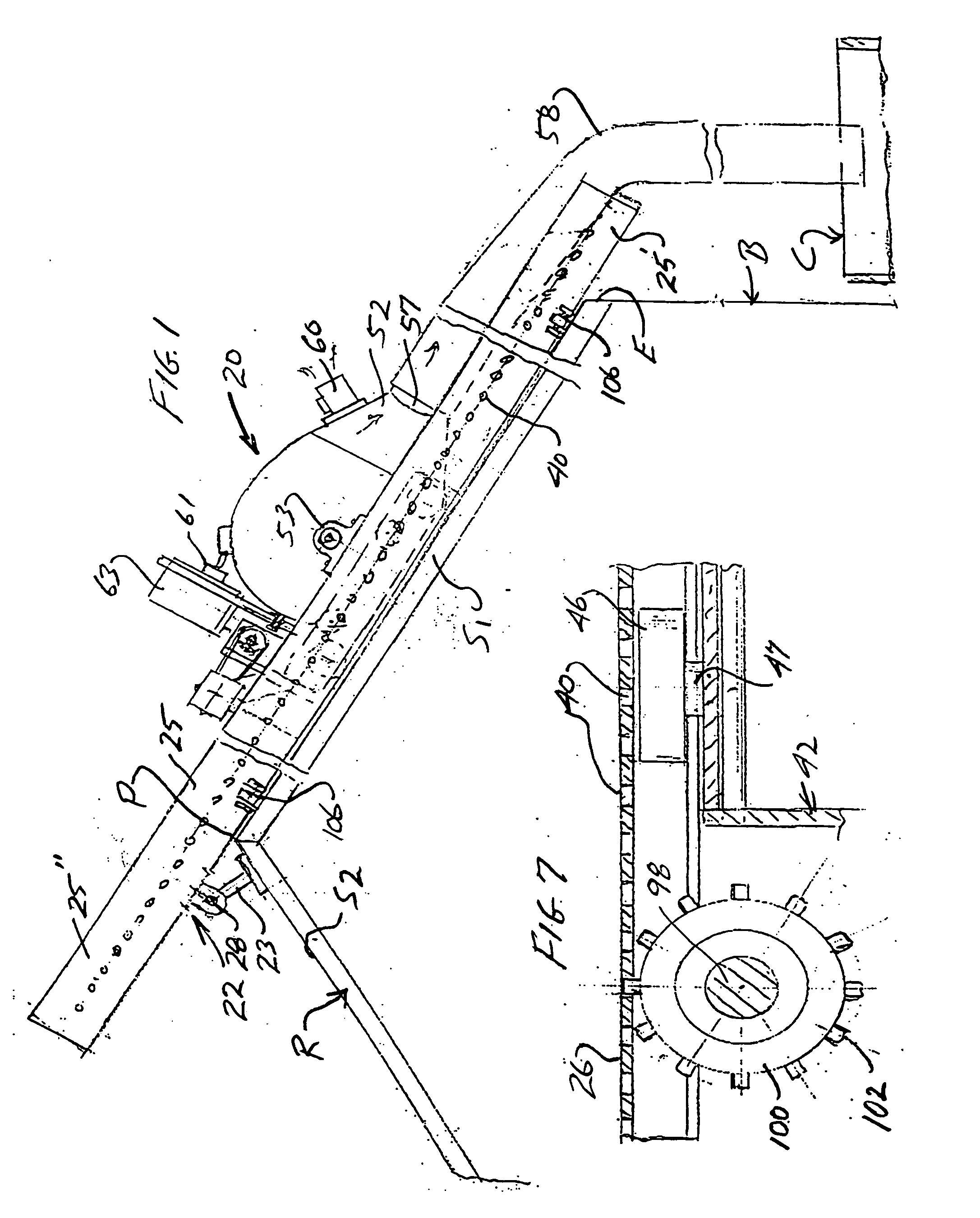
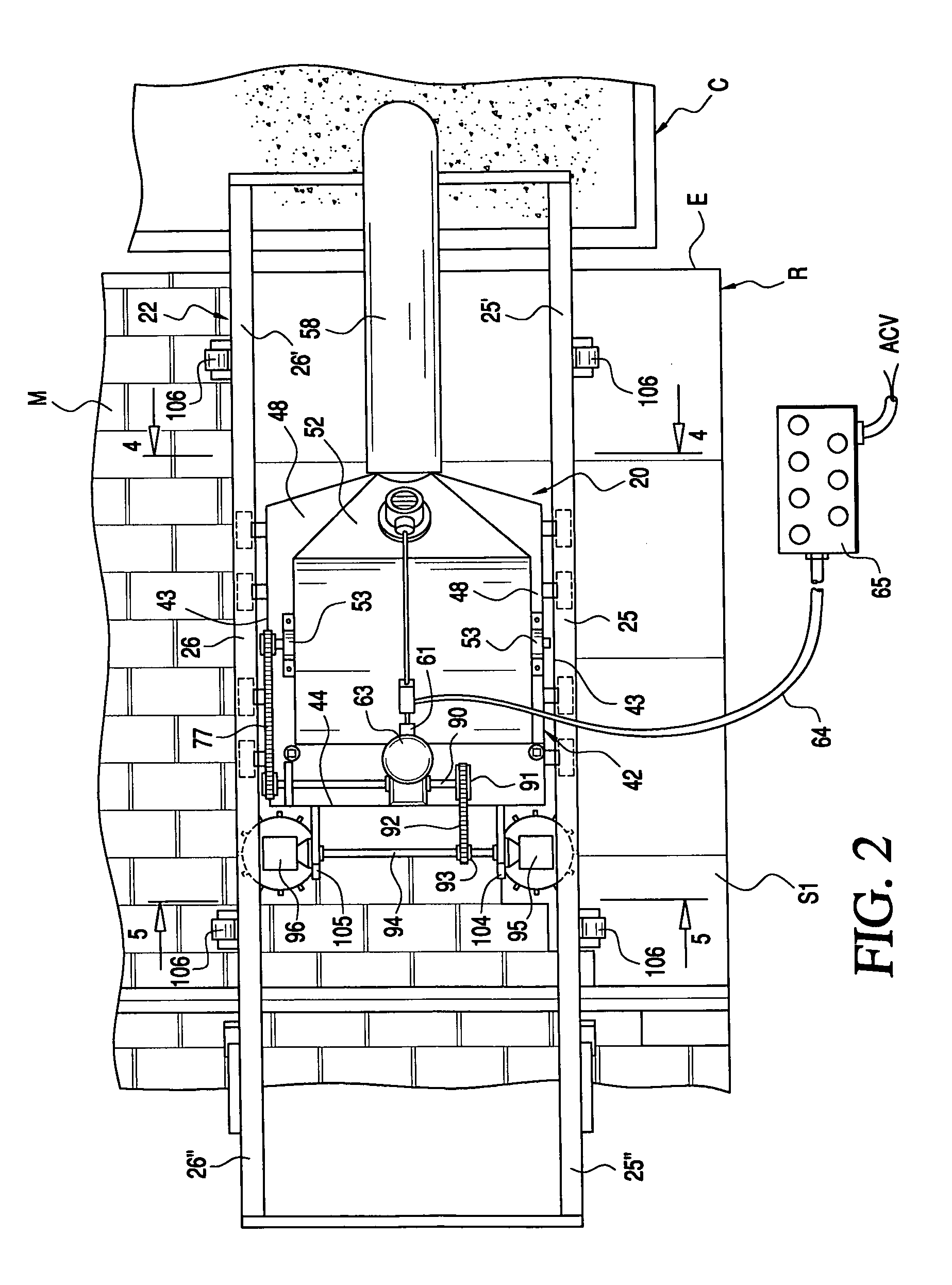
[0008] The present invention is directed to an automated shingle removing machine that overcomes the problems associated with the prior art roofing shingle removing machines and manually operated tools or implements and provides a safe and labor efficient manner of removing old roofing materials in order to prepare structures for new roofing shingles and other materials. The invention is directed to a machine that may be quickly placed into service on most roofs regardless of their pitch because the machine is not manipulated or physically guided by an individual during use. Rather, the shingle removing machine of the invention is mounted on a roof supported guide rail assembly and is movable along opposite rails of the assembly under its own power.
[0009] In the preferred embodiment the machine includes a primary frame mounted on four sets of oppositely oriented rollers or wheels that are designed to ride within opposing u-shaped guide rails or tracks of the guide rail assembly. The u-shaped guide rails are suspended from pivotally adjustable brackets or suspension members that engage an opposite side of a roof from where the guide rails are in use. There is a first set of roller on each side of the primary frame for engaging an upper surface of the guide rails and a second set on each side of the primary frame for engaging a lower surface of the guide rails. The u-shaped rails positively orient the machine as it moves along the rails under power provided by a driving device that may be an engine, motor or other suitable power source. In the preferred embodiment, the power source is an electric motor that is supported by the primary machine frame, however, hydraulic or pneumatic motors that receive liquid or air from a source that may be remotely spaced from a roof being work on may be used as well as petroleum or gas powered engines. The electric motor is preferably connected to a remote controller, either by way of a direct cord-like or cable connection or by a remote controller capable of sending high frequency or other signals to an on board motor controller. In this manner, the machine may be remotely operated from the ground during use, thereby reducing the risk of injury to the machine operator.
[0016] It is a primary object of the present invention to provide a shingle removing machine which may be easily placed on a guide rail assembly that includes a pair of opposing guide rails that are suspended over a hip of a roof structure and thereafter controlled by an operator either on the roof or at a remote location, such as at ground level adjacent the structure being worked on, such that the machine is operable to remove old roofing shingles, nails, roofing felt, tar paper or the like without direct physical manipulation.
[0017] It is another object of the invention to provide a safe and expedient manner of removing old roofing materials wherein the materials are automatically conveyed to a collection receptacle as they are removed thus facilitating cleanup of a work site.
[0020] It is another object of a varied embodiment of the invention to provide a machine for removing old roofing materials and fasteners from a roof wherein the machine and a guide rail assembly on which the machine is positively guided and supported may be automatically shifted relative to a roof surface so that substantially an entire surface of a section of roof may be stripped without having to manually manipulate the machine or the supporting rail assembly.

Problems solved by technology

Hand tools for facilitating the removal of roofing shingles have long been known, however, such tools not only require a great deal of physical strength, but their use is labor intensive and often unsafe.
Roofing, by its very nature, is a hazardous activity and, on steeply pitched roofs, it is extremely difficult for roofers to adequately and safely manipulate hand held shingle removal tools to remove old shingles and roofing nails or other fasteners.
Unfortunately, such machines are difficult to manipulate and often totally unsuitable for use on steeply pitched roofs.
Also, manipulating any type of powered machinery on a roof is extremely dangerous and unsafe.

Method used


Image

  • Automated roofing material removal machine and method
  • Automated roofing material removal machine and method
  • Automated roofing material removal machine and method

Examples


Embodiment Construction

[0040] With continued reference to the drawing figures, the invention will be described as being used to remove shingles, roofing felt, tar paper, fasteners and other roof covering materials “M” from a roof “R”. The roof is shown as being a hip roof having oppositely pitched roof sections “S1” and “S2” that meet at the peak or ridge “P” of the roof. The invention can be used on substantially any roof regardless of the roof pitch and can be controlled remotely by an operator from a position of safety.

[0041] The invention includes a roofing material removal machine 20 that is guided and supported by a guide rail assembly 22 that, in the embodiments shown, includes a pair of suspension legs 23 from which a pair of guide rails or tracks 25 and 26 are suspended. As shown in FIGS. 1 and 2, the guide rails extend downwardly along roof section “S1” in spaced but parallel relationship with respect to one another. The lower portions 25′ and 26′ of the guide rails extend or are cantilevered o...


PUM

PropertyMeasurementUnit
poweraaaaaaaaaa
areaaaaaaaaaaa
physical strengthaaaaaaaaaa

Abstract

A roofing material removal machine and method for removing roofing materials wherein the machine travels along guide rails mounted on a roof surface and roofing material lifting elements carried by the machine are operated to lift the roofing materials as the machine moves along the guide rails after which the removed materials are conveyed to a collection receptacle. A remote control device may be used to control power to and movement of the machine along the guide rails.

Description

BACKGROUND OF THE INVENTION [0001] 1. Field of the Invention [0002] The present invention is generally directed to machines for removing old roofing shingles, roofing felt, tar paper, nails and the like from building structures and more particularly to such a machine that is movably guided on guide rails that are mounted on a shingled roof. The machine includes a plurality of cutter heads that are mounted on a drive shaft driven by a power source carried by the machine. Drive elements mounted on the machine are also powered by the power source and move the machine relative to the guide rails. Removed shingles and other debris are thrown by the cutter heads to a discharge area of the machine housing from which they are pneumatically conveyed and / or conveyed by gravity to a collection receptacle or truck positioned adjacent the building from which the old roofing materials are being removed. The machine is preferably remotely controlled for operator safety. [0003] 2. Brief Description...

Claims


Application Information

Patent Timeline
Patent Type & Authority Applications(United States)
IPC IPC(8): E21C25/00
CPCY10T408/03E04D15/003
Inventor BROWN, METHUSELAH (MATT)
Owner ARREL TECH
Learn More