Light source system and an image projection system

a technology of light source system and image projection system, which is applied in the field of light source system, can solve the problems of insufficient light intensity, waste of part of the illumination of the lamp, and loss of coupling between the various components of the system, and achieve good coupling and light coupling

Inactive Publication Date: 2007-07-19
SHARP KK
View PDF18 Cites 32 Cited by
  • Summary
  • Abstract
  • Description
  • Claims
  • Application Information

AI Technical Summary

Benefits of technology

[0042] Prior art illumination systems having a reflector disposed adjacent to the light source, such as the illumination system in FIG. 13, produce a direct image of the light source (which may be at infinity if the reflector is shaped to emit collimated light). A typical light source emits light with an intensity that varies over the area of the light source, and these intensity variations will be reproduced in the direct image of the light source produced by the reflector. It is therefore necessary to provide the integrator 22 to eliminate these variations in intensity, and provide a light output at the output face 25 of the integrator that has an intensity that is, as far as possible, uniform over the output face of the integrator. Any variations in intensity over the output face of the integrator will result in variations in intensity over the area of the projected image.
[0043] A non-imaging optical element as used in a light source system of the present invention does not, in contrast, produce a direct image of the light source. The light output at the output surface of the non-imaging optical element has an intensity that is substantially uniform over the area of the output surface, and the integrator 25 of the prior art may thus be omitted. A light source system of the invention is therefore smaller and lighter than a prior art system of the same output power.
[0044] A further feature of the invention is that the light source is positioned within the non-imaging optical element. The non-imaging enclosure is optical element so as to direct light to the output surface of the optical element, so that there is very good coupling between the light source and the output surface of the non-imaging optical element. In contrast, in a conventional system having a lamp, a reflector and an integrator rod there are unavoidable coupling losses between the lamp and the integrator rod. Moreover, it is necessary to align the lamp and reflector with the integrator rod in order to provide the greatest possible coupling of light into the integrator, and this can be difficult and time-consuming to do. In the present invention, however, no alignment of a lamp to an integrator rod is required. The light source is positioned in the non-imaging optical element, and may be secured at its desired location within the optical element—and good coupling of light to the output surface of the non-imaging optical element is assured.
[0046] The non-imaging optical element may be closed at the first end. This prevents light being lost through the first end of the optical element.

Problems solved by technology

A strong disadvantage of this design is the coupling losses between the various components in the system.
However, the light intensity is insufficient in the red wavelength region of the spectrum above 600 nmn and this is known as a “red deficiency”.
However, if the light intensity in the blue and green wavelength regions is reduced to provide light intensity balance with the light intensity in the red wavelength region, by for example, dimming the G and B channels or increasing the angular size of the red segment of a colour wheel, part of the illumination from the lamp is wasted.
However, the luminous efficiency of a xenon lamp is lower than that of a UHP lamp.
Thus, the power consumption of a xenon lamp is markedly higher than that of a UHP lamp of equivalent brightness, and this is a disadvantage in many applications.
They all share the disadvantage that additional power is needed for the additional light source.
Also, whenever additional light is added to a projector system, either the entrance aperture of the system must be made larger (leading to less efficient light usage), or a spectrally or angularly selective reflector must be used (leading to some loss of light from the UHP lamp).
There are a number of disadvantages of this approach.
A high power laser is required, adding to the expense of the system and imposing requirements for cooling and power.
The illumination system is bulky, which substantially increases the size of the image projector, and it is inefficient.
There are a number of disadvantages of this approach, associated with the size of the transparent area at the entrance face of the integrator rod.
If only a small area of the input face 3a of the integrator rod is transparent, then recycled light is efficiently reflected back towards the exit face 3b of the integrator rod; in this case, however, light can not be coupled efficiently into the integrator rod from the lamp.
The étendue of the light emitted by the integrator is therefore increased by a factor of three, making projector design more difficult and lowering the light efficiency.
Although colour re-capture described in this prior art increases light throughput, it does not reduce the red deficiency of the illuminator and so it does not improve the colour balance of the projected image.
As the fluorescent material of a wavelength converting filter in this prior art emits over the full solid angle subtended by the filter, the collection efficiency of the converted spectral component is very low since the projection system is designed for a limited angular cone of illumination light.
Much less than 1% of light from an isotropic source, such as a wavelength-converting filter, would be emitted into this cone so that over 99% of the output of a wavelength-converting filter would be wasted.
This prior art LCD projector also does not use polarisation conversion and homogenisation optics and suffers from low efficiency of light utilisation and brightness non-uniformity.
Furthermore, due to the low broadband absorption cross-section of rare-earth ions, a substantial part of the UV and IR radiation propagates through the integrator rod 22 unconverted, and is lost from the system.
The problem of the selection of a small acceptance angle from an isotropic source, which leads to low efficiency in patent applications JP 2001-264880 and JP2002-90883, is therefore reduced.
A further difficulty with this proposal is the low absorption cross-section of the fluorescent material integrated into the glass rod 3.
The efficiency of UV light utilisation is low.
If fluorescent material is highly concentrated in an attempt to solve this problem, the efficiency of photoluminescence suffers due to concentration quenching.
Again this tapered structure is separate from the light source 1 (an arc tube) and light must therefore be coupled into the tapered integrator rod 13 from the light source, leading to unavoidable loss of light.

Method used


Image

  • Light source system and an image projection system
  • Light source system and an image projection system
  • Light source system and an image projection system

Examples


Embodiment Construction

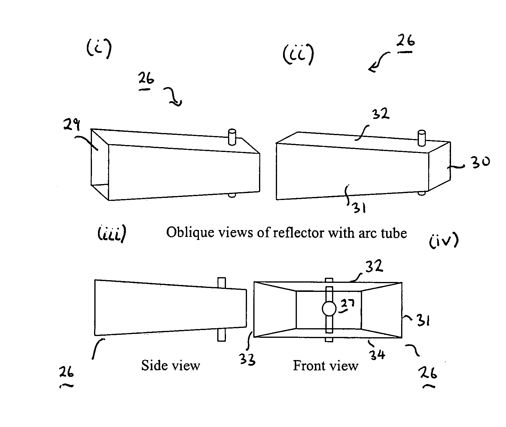
[0097]FIGS. 8a(i) to 8a(iv) illustrate a light source system 26 according to a first embodiment of the present invention. The light source system comprises a light source 27 and an optical element 28 having a first end that is preferably closed and a second end that is open to define an output face 29. The light source 27 is mounted within the optical element 28, at or near the first end of the optical element, and is thereby spaced from the output face 29. The light source 27 may consist of, for example, a discharge tube, and may for example consist of a high-pressure discharge tube of the type well known and currently used in projectors. FIGS. 8a(i) and 8a(ii) are perspective views of the light source system, FIG. 8a(iii) is a side view of the light source system, and FIG. 8a(iv) is an end view of the light source system, looking into the optical element from the output face.

[0098] The optical element 28 is a non-imaging optical element. The optical element 28 does not form a rea...


PUM


Abstract

A light source system comprises a light source disposed within a non-imaging optical element. The non-imaging optical element does not produce a direct image of the light source, and the output light field at the output surface of the non-imaging optical element has an intensity that is substantially uniform over the area of the output surface. A light source system of the invention is therefore smaller and lighter than a prior art system of the same output power, since there is no need to provide further components, such as an integrator, to homogenise the output light field.

Description

FIELD OF THE INVENTION [0001] This invention relates to a light source system, for example for use in an image projection system, and particularly to a light source system with improved brightness and colour balance. It also relates to an image projection system. BACKGROUND OF THE INVENTION [0002] Image projection systems have been used for many years to project motion and still pictures onto screens for viewing. Presentations using multimedia projection systems are widely used to deliver information in diverse fields, such as sales, demonstrations, business meetings and education. [0003] Many types of projection systems use non-emitting spatial light modulators in combination with an illumination source to generate an image. Colour image projection displays operate on the principle that colour images are produced from 3 primary colours, red (R), green (G) and blue (B), projected onto a screen, either at the same time or sequentially in time. The light of wavelength bands correspond...

Claims


Application Information

Patent Timeline
Patent Type & Authority Applications(United States)
IPC IPC(8): G03B21/26
CPCH04N9/3117G03B21/26
Inventor COPNER, NIGEL JOSEPHEVANS, ALLAN
Owner SHARP KK
Why Eureka
Try Eureka