Stereoscopic imaging apparatus incorporating a parallax barrier

a parallax barrier and imaging apparatus technology, applied in the field of autostereoscopic viewing systems, can solve the problems of requiring special spectacles, reducing the efficiency of viewing, so as to achieve the effect of increasing efficiency

Inactive Publication Date: 2007-07-19
UNIPIXEL DISPLAY
View PDF8 Cites 72 Cited by
  • Summary
  • Abstract
  • Description
  • Claims
  • Application Information

AI Technical Summary

Benefits of technology

[0043] In a separate and independent aspect of the invention, an apparatus is configured to provide a stereoscopic image for viewing by a viewer having two eyes without the need for special spectacles and with increased efficiency. More particularly, the apparatus includes a generally planar display comprising a two-dimensional array of uniformly spaced pixels and it further includes a generally planar parallax barrier having an area substantially coextensive with the display and spaced a prescribed uniform distance from the display, on the side of the display opposite the viewer. The parallax barrier includes alternating first and second vertically oriented regions. The first vertically oriented regions are configured to tran...

Problems solved by technology

This traditional arrangement has the inherent disadvantage that the use of a single filter color for each eye causes the perceived image, although three-dimensional, to have very little, if any, residual color information.
It sometimes is possible to see some color on traditional anaglyph images; however, the amount of color is severely limited and the perceived images are largely seen as being monochromatic.
Both traditional and modern full-color anaglyphic arrangements have the disadvantage of requiring the use of special spectacles.
This has the unintended consequence of causing a subtle negative focus shift, in effect, introducing the symptoms of far-sightedness.
In fact, the red-filtered image is noticeably out of focus in most cases, due to the focus accommodation limits of all but the most youthful viewers.
Plastic-mounted filters have the same poor performance as paper-framed spectacles.
Another inherent disadvantage of anaglyphic spectacles is that color gel filters are incapable of separating the two images perfectly, thus producing “crosstalk,” which has the appearan...

Method used


Image

  • Stereoscopic imaging apparatus incorporating a parallax barrier
  • Stereoscopic imaging apparatus incorporating a parallax barrier
  • Stereoscopic imaging apparatus incorporating a parallax barrier

Examples


first embodiment

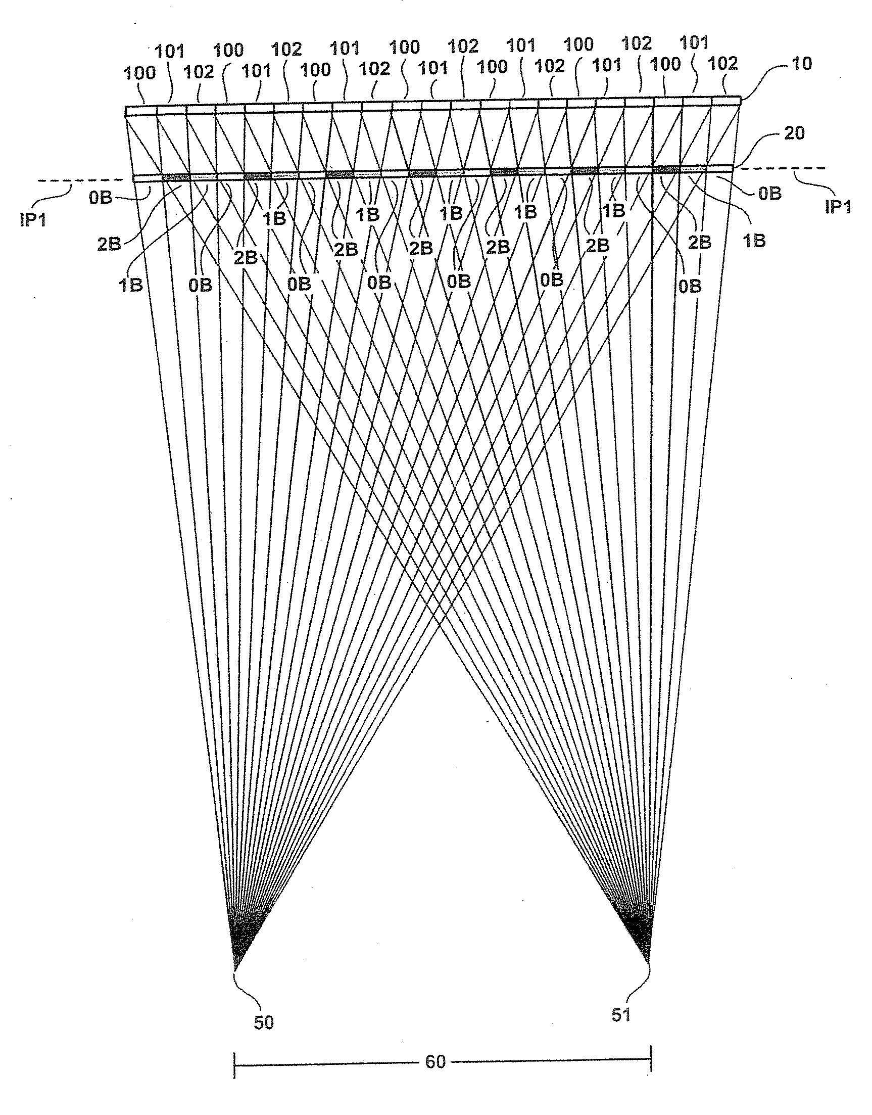
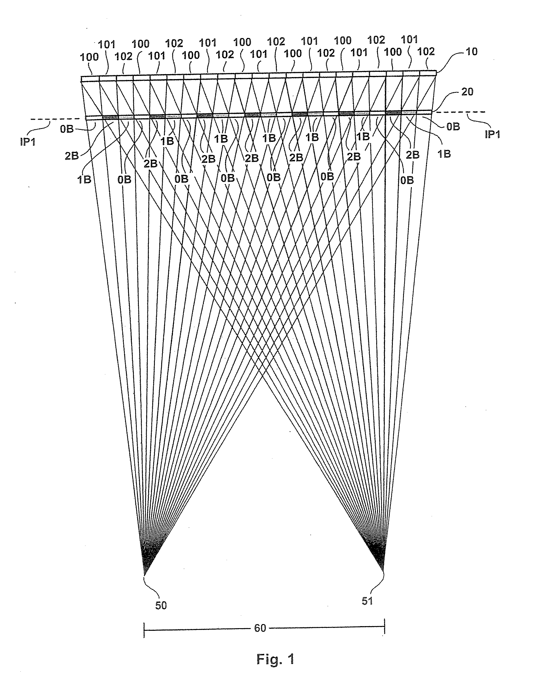
[0136] With reference now to FIG. 1 of the drawings, there is shown the invention, including a display 10 that is divided into a first region 100 representing a first sub-pixel emitting light of a first spectral range (e.g., red), a second region 101 representing a second sub-pixel emitting light of a second spectral range (e.g., green), and a third region 102 representing a third sub-pixel emitting light of a third spectral range (e.g., blue). Typically, the common display colors of red, green, and blue are referred to as an RGB display.

[0137] Also shown in FIG. 1 is a frontal parallax barrier 20 that is divided into a first light-filtering region 2B, for blocking light emanating from both sub-pixel 100 and sub-pixel 101; a second light-filtering region 1B, for transmitting light emanating from sub-pixel 101 while blocking light emitted from sub-pixel 102; and a third light-filtering region 0B, for transmitting light emanating from both sub-pixel 102 and sub-pixel 100.

[0138] The p...

second embodiment

[0153] With reference now to FIG. 6, there is shown the invention, in which a parallax barrier is placed not at the first intersection plane, but rather at an alternative intersection plane, while still operating at the same viewing distance between the display 10 and the viewer's eyes 50, 51. For instance, as described earlier, the transparent substrate (not shown in FIG. 6) overlaying the pixels of the display 10 can sometimes be thicker than the distance between the pixels and the first intersection plane IP1. Rather than attempt to embed a parallax barrier within the substrate, the embodiment of FIG. 6 instead places the parallax barrier 20 at the second intersection plane IP2. This placement requires a different configuration for the light-filtering regions 2B, 1B, and 0B, as compared to their configuration in the first intersection plane IP1.

[0154] As shown in FIG. 6, the parallax barrier 20 is divided into first light-filtering regions 2B, for blocking light emanating from bo...

third embodiment

[0160] With reference now to FIG. 11, there is shown the invention, in which two separate frontal parallax barriers 20 and 30 are included, for providing anaglyphic auto-stereoscopic viewing. More particularly, the parallax barrier 20 includes light-filtering regions 2Bo1B, for blocking light emanating from the sub-pixels 101 and optionally blocking light emanating from the sub-pixels 100, and the second parallax barrier 30 likewise includes light-filtering regions 2Bo1B, for blocking light emanating from sub-pixels 102 and, optionally, for blocking light emanating from the sub-pixels 100. It should be noted that the two frontal parallax barriers each can be located on its own substrate or, alternatively, can be located on the front and back sides of a single substrate.

[0161] The proper placement of the parallax barrier 20 and its light-filtering regions 2Bo1B ensures that the viewer's left eye 50 cannot see the sub-pixels 101 and that the viewer's right eye 51 cannot see the sub-pi...


PUM


Abstract

An improved apparatus is disclosed for providing a stereoscopic image for viewing by a viewer, with improved resolution. The apparatus includes a generally planar display comprising a two-dimensional array of uniformly spaced pixels, and it further includes a generally planar parallax barrier having an area substantially coextensive with the display and spaced a prescribed uniform distance from the display. The pixel array includes a first set of sub-pixels controllable to project light in a first spectral color, a second set of sub-pixels controllable to project light in a second spectral color, and a third set of sub-pixels controllable to project light in a third spectral color, and the parallax barrier includes a repeating pattern of vertically oriented regions configured to transmit light to the viewer's first eye along light paths defined from only the first set of sub-pixels and to transmit light to the viewer's second eye along light paths defined from only the second and third sets of sub-pixels.

Description

CROSS-REFERENCE TO RELATED APPLICATION [0001] Priority is claimed from provisional Application No. 60 / 750,882, filed Dec. 15, 2005, which is incorporated herein by reference.BACKGROUND OF THE INVENTION [0002] 1. Field of the Invention [0003] The present invention relates in general to auto-stereoscopic viewing systems for use in conjunction with flat panel displays. More particularly, the invention relates to a system for viewing anaglyphic imagery without the use of spectacles, which can be used concurrently by one or more viewers to experience the perception of depth. [0004] 2. Description of the Prior Art [0005] Existing stereoscopic display systems using binocular parallax information are mainly categorized into two groups. In the first group, stereoscopic vision is achieved using a pair of special spectacles, e.g., polarizing spectacles, LC shutter spectacles, or anaglyphic spectacles, whereas in the second group, stereoscopic vision is achieved using a specific optical member,...

Claims


Application Information

Patent Timeline
IPC IPC(8): H04N13/00G02B27/22H04N15/00G02B30/30
CPCG02B27/2214H04N13/0409H04N13/0456H04N13/0422H04N13/0411H04N13/312H04N13/324H04N13/31H04N13/361G02B30/30H04N3/00G02B30/27
Inventor MEHRLE, MICHAEL
Owner UNIPIXEL DISPLAY
Why Eureka
Try Eureka