Turbine airfoil with improved cooling

Active Publication Date: 2007-07-19
RAYTHEON TECH CORP +1
View PDF9 Cites 10 Cited by
  • Summary
  • Abstract
  • Description
  • Claims
  • Application Information

AI Technical Summary

Benefits of technology

[0006] A baffle may be inserted into the airfoil to provide the fluid outlets. The baffle may include the plurality of fluid outlets arranged in a pattern to focus impingement jets on the web regions between each adjacent pair of minicores. The dimensions and spacing of the impingement outlets ar

Problems solved by technology

Because of the high heat fluxes associated with these cooling circuits, large thermal gr

Method used


Image

  • Turbine airfoil with improved cooling
  • Turbine airfoil with improved cooling
  • Turbine airfoil with improved cooling

Examples


Embodiment Construction

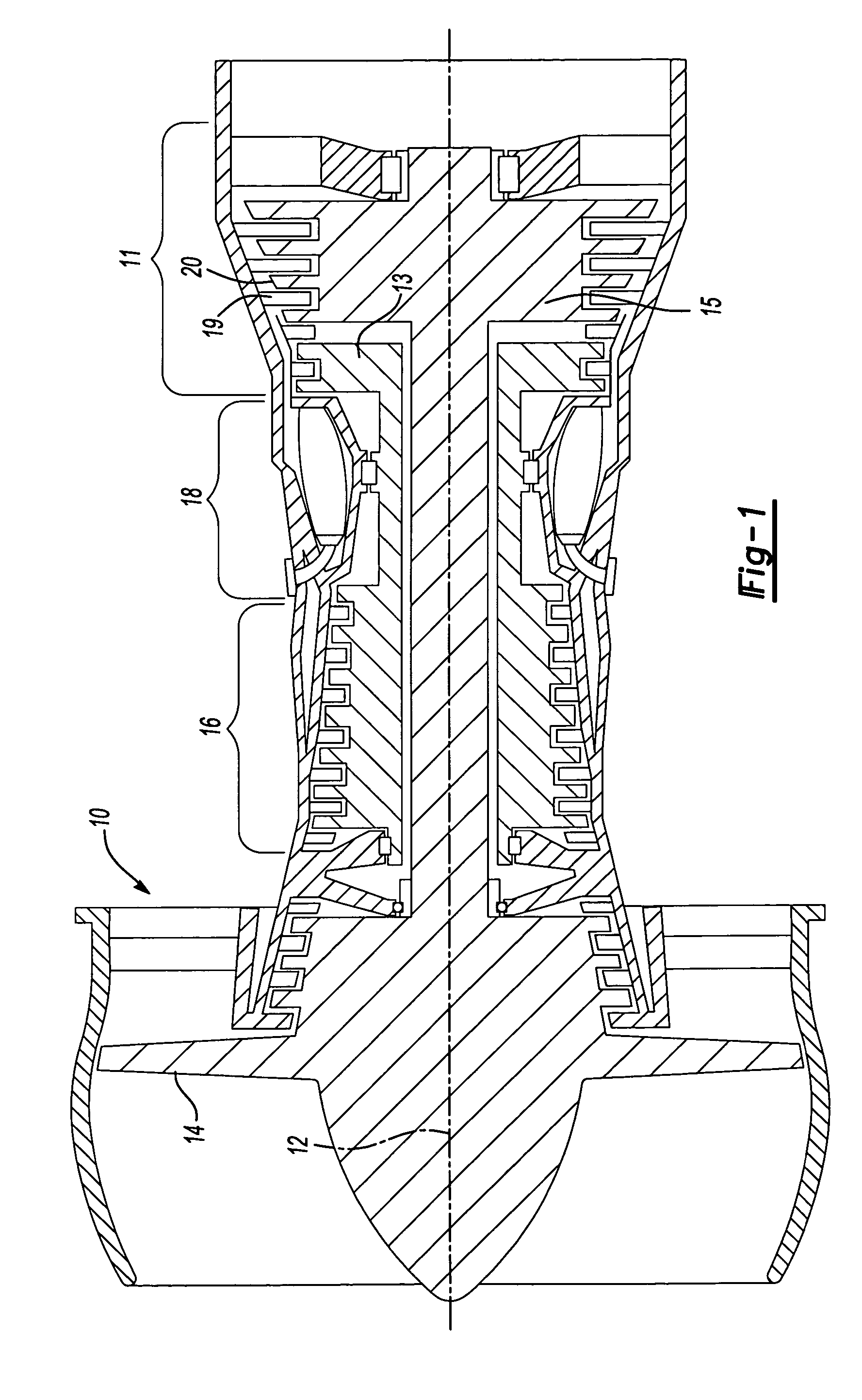
[0014]FIG. 1 shows a gas turbine engine 10, such as a gas turbine used for power generation or propulsion, circumferentially disposed about an engine centerline or axial centerline axis 12. The engine 10 includes a fan 14, a compressor 16, a combustion section 18 and a turbine 11. As is well known, air compressed in the compressor 16 is mixed with fuel that is burned in the combustion section 18 and expanded in turbine 11. The turbine 11 includes rotors 13 and 15 that rotate in response to the expansion, driving the compressor 16 and fan 14. The turbine 11 compresses alternating rows of turbine blades 20 and vanes 19. FIG. 1 is a somewhat schematic presentation for illustrative purposes only and is not a limitation on the instant invention, which may be employed on gas turbines for electrical power generation, aircraft, etc. Additionally, there are various types of gas turbine engines, many of which could benefit from the present invention, which is not limited to the design shown. ...


PUM


Abstract

A turbine airfoil includes an outer wall and a plurality of cooling passages or minicores formed in the outer wall. A web separates each adjacent pair of the minicores. In order to provide more effective, even cooling of the airfoil, a baffle inside the airfoil includes a plurality of outlets aligned with the webs. The fluid outlets direct the cooling fluid directly onto the web. The cooling fluid then flows through the minicores and out through exits in the minicores.

Description

[0001] This invention was made with Government support under N00019-02-C-3003 awarded by the United States Navy. The Government has certain rights in this invention.BACKGROUND OF THE INVENTION [0002] The present invention relates generally to gas turbine engines and more particularly to cooling a turbine airfoil. [0003] In operation, turbine airfoils are routinely exposed to temperatures well above their material limits. In existing engines, air from the compressor section of the turbine engine is used to cool the airfoil. Cast-in passages, known as minicores, are embedded in the airfoil wall to enhance convective cooling. Because of the high heat fluxes associated with these cooling circuits, large thermal gradients arise and the airfoil becomes susceptible to thermal mechanical fatigue cracking. To reduce thermal strains, a web is required between the minicores to stiffen the airfoil wall. The presence of the web, however, creates an area of lower heat flux compared to that of the...

Claims


Application Information

Patent Timeline
IPC IPC(8): F01D5/18
CPCF01D5/186F01D5/189F05D2260/2214F05D2260/2212Y02T50/676Y02T50/60F01D5/00F01D5/18
Inventor DEVORE, MATTHEW A.PAAUWE, CORNEIL S.
Owner RAYTHEON TECH CORP
Why Eureka
Try Eureka