
Electromuscular incapacitation device and methods

a technology of electromagnetic incapacitation and electrodes, which is applied in the field of electromagnetic incapacitation devices and methods, can solve the problems of increasing morbidity and mortalities, little improvement or change in emi approach, and little objective laboratory data available describing the physiological effects of stun devices, so as to achieve effective and enhanced incapacitation and less chance of permanent nerve and muscle injury

Inactive Publication Date: 2007-07-19
AEGIS IND INC
View PDF9 Cites 35 Cited by
  • Summary
  • Abstract
  • Description
  • Claims
  • Application Information

AI Technical Summary

Benefits of technology

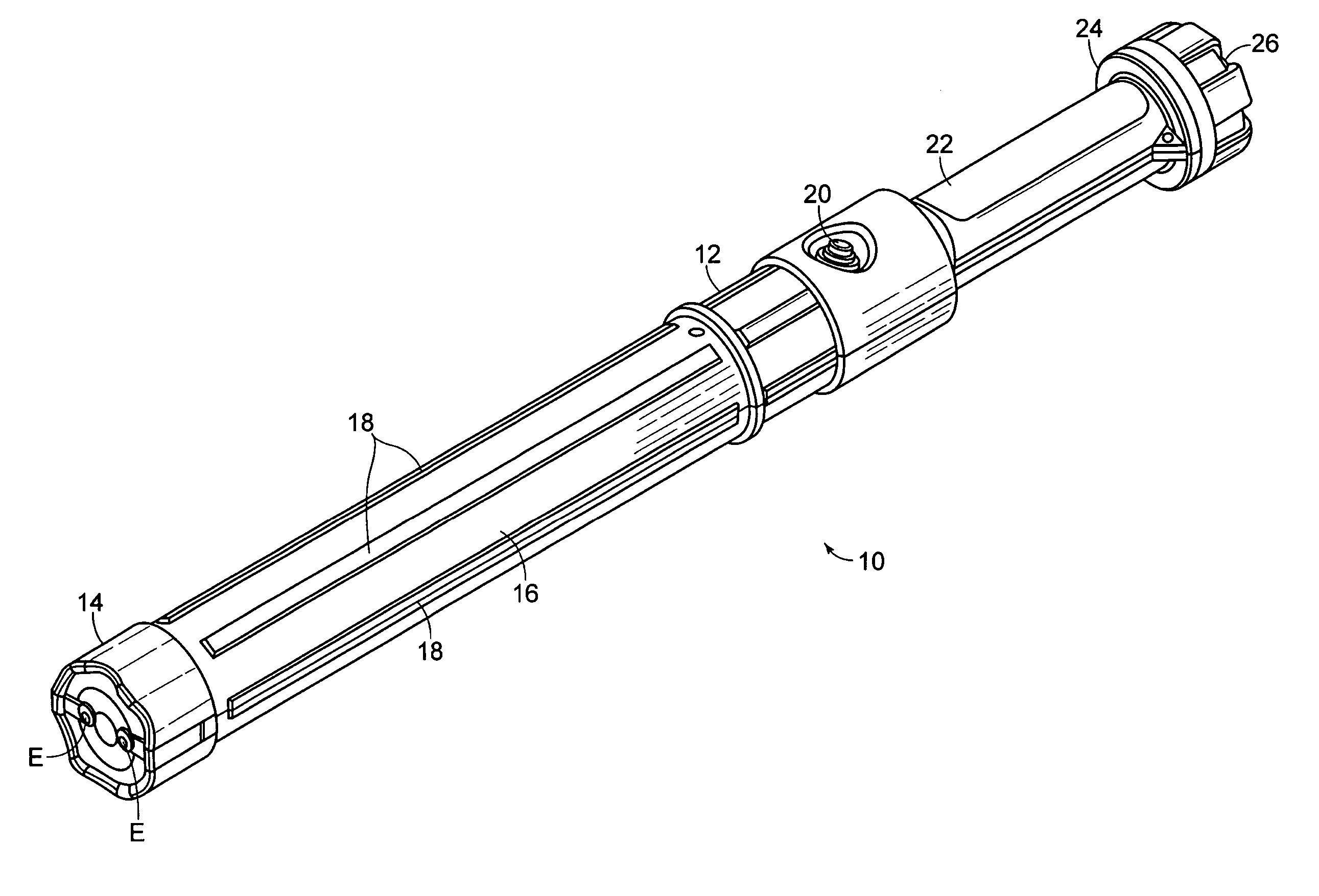
[0008] It is contemplated by the inventors that studies of the physiologic effects of EMI stimuli may be crucial to developing an improved EMI device with non-injurious features for both healthy and vulnerable populations. Certain biologically-based studies may be used, for example, to improve the actual hardware-delivered EMI stimulus leading to more effective and enhanced incapacitation with less chance of permanent nerve and muscle injury to a subject. This would be particularly useful information, especially regarding subjects who may be at risk for adverse reaction to a full stun incident including the elderly, mentally disturbed, pregnant, very young, intoxicated, and otherwise health-compromised individuals. It would be highly desirable to have an optimized, non-subcutaneous, point-of-contact EMI capacity suitable for use on a wide variety of persons and in various circumstances.
[0009] The present invention offers improvements over typical stun gun systems by offering a locationally precise point-of-contact capability of variable duration and incapacitation effect using an improved EMI stimulus based on biologically relevant studies.
[0011] The improved device utilizes electrical current waveforms to maximize neuromuscular mechanisms responsible for EMI and minimize local tissue damage or deleterious and non-reversible general responses which result from local tissue damage.
[0013] In one aspect, the invention relates to an EMI device for providing an electrical stimulus signal with an optimum electric waveform and amplitude to produce selectively an electric charge of stunning capability. Embodiments of the above aspect may include the following, individually and in various combinations: (a) any of the series of pulses having different frequencies out of which at least one pulse has a repetition rate in the range of about 5-1000 pulses per second (i.e., Hz); (b) pulse duration that ranges from about 3-1000 microseconds; (c) pulse ionization potential that delivers charge in the range of about 20 microcoulomb to 1500 microcoulomb; (d) pulses which vary in shape such as sinusoidal, square, triangular or sawtooth; (e) energy content which ranges from about 0.001-0.5 joule / pulse; (f) RMS current in ranges smaller than about 400 mA; (g) duty cycle of about 0.005% to 5%; (h) circuitry that utilizes solid state semiconductors for pulse power switching for improved switching speed, high reliability, low degradation, lengthened life, low cost, high repetition rate, low losses, and high voltage and current rating over conventional capacitor discharge topologies (e.g. thyratron, ignitron, or spark gap); (i) at least two electrodes; and (j) voltage in the range of about 100 V-100 kV.

Problems solved by technology

Notwithstanding the history of stun devices, there has been little improvement or change in the EMI approach.
Very little objective laboratory data is available describing the physiological effects of stun devices.
As a result of the increased usage and deployment of EMI devices, a growing number of individuals are presenting electrical injuries related to the use of such devices and a growing number of morbidities and mortalities are being observed.
Moreover, the application of electric currents to a live subject may cause acidosis, due to incomplete or inconsistent muscular contraction.
Acidosis occurs when the body is incapable of properly clearing lactic acid build-up within areas of the body, a condition that may lead to death in extreme cases.
Some types of current (e.g., direct current, DC) can cause little or no injury at low levels and increasing amounts of damage and disruption of muscle control at higher levels.

Method used


Image

  • Electromuscular incapacitation device and methods
  • Electromuscular incapacitation device and methods
  • Electromuscular incapacitation device and methods

Examples


example 1

Determination of Optimized Frequency to Achieve Tetany in a Mammal

[0054] This experiment shows that the optimized frequency of a waveform to produce tetany in a subject mammal is in a range from about 50 Hz to about 70 Hz.

[0055] Voltage was maintained while the frequency of the waveform was varied between 1 Hz-1000 Hz, and electromyogram (EMG) data from the mammals was recorded for each stimulus frequency (i.e., 1, 2, 5, 10, 20, 50, 60, 70, 100, 200, 500, 1000 Hz). Stimulating needle electrodes were placed on either side of a femoral nerve of a subject approximately 1 cm apart, while recording electrodes were placed about 8 cm apart, one on a knee and the other in a middle part of the rectus femorus muscle. Recordings were taken from both ipsi- and contralateral sides of the body. The stimulus pulse amplitudes were maintained at 60 V for each frequency tested and duration of the waveform pulse was 0.1 ms in all cases. The waveforms tested comprised a generally square shape pulsed...

example 2

EMI Produced by Waveform Generated by the Circuit of FIGS. 3A-3B

[0060] This example demonstrates that the waveform generated by the circuit depicted in FIGS. 3A-3B produces EMI in a mammal.

[0061] Stimulating electrodes were fabricated out of 3 mm diameter stainless steel. Care was taken in the design and fabrication process to promote uniform charge distribution during stimulation. Two planar and two hemispherical electrodes were fabricated. The hemispherical electrodes were filed while turning in a drill press until a ball shape was achieved. Layers of primer and enamel paint were applied to all surfaces. The paint was allowed to cure at about 40° C. for 1 hour. To create the planar electrodes, paint was removed from one end with 600 grit sandpaper and the surface was polished with 4-0 emery paper until the surface was shiny. Paint was removed and surfaces were polished on the hemispherical electrodes in the same manner. An additional 2 mm of paint was removed from the base of th...

example 3

Acute Study of Effects of a Waveform on Subject

[0065] The purpose of the experiment was to characterize the acute effects of damped pulsed DC electric fields as produced by the circuit of FIGS. 3A-3B on living tissue.

[0066] Several experiments were performed in vivo on mammals, using the circuit in accordance with that depicted in FIGS. 3A-3B. An EMI test device utilizing the circuit in accordance with that depicted in FIGS. 3A-3B was used to deliver electrical signals to the subjects comprising 0.15 μF capacitance. The device was held in a vertical orientation by clamping a 2″ PVC pipe to the stand and was assembled such that the device was sheathed in the pipe to permit a uniform downward force on the device resulting from a total mass of 1.5 kg. A 12.0 VDC, 800 mA power supply was used as the power source. The subjects were anesthetized during all electrical discharges and all subsequent monitoring sessions.

[0067] Compound muscle action potential (CMAP) recordings were obtain...


PUM


Abstract

Incapacitation of a mammalian subject results from the application of a pulsed, low-power electric waveform. The waveform is applied to the subject at a frequency and over a time period sufficient to induce involuntary muscular contraction. Additionally, the contraction causes limited lactic acid production and is non- or minimally-injurious to the subject's tissues. A device utilizing such a waveform is designed to control or otherwise subdue an individual.

Description

CROSS-REFERENCE TO RELATED APPLICATIONS [0001] This application claims priority to and incorporates by reference herein in their entireties, the following: U.S. Provisional Patent Application Ser. No. 60 / 794,919, filed on Apr. 24, 2006; U.S. Provisional Patent Application Ser. No. 60 / 794,325, filed on Apr. 21, 2006; U.S. Provisional Patent Application Ser. No. 60 / 764,787, filed on Feb. 2, 2006; U.S. Provisional Patent Application Ser. No. 60 / 764,785, filed on Feb. 2, 2006; U.S. Provisional Patent Application Ser. No. 60 / 736,603, filed on Nov. 14, 2005; and U.S. Provisional Patent Application Ser. No. 60 / 736,132, filed on Nov. 11, 2005. [0002] This application also claims priority to and is a continuation-in-part of U.S. patent application Ser. No. 11 / 208,762, filed on Aug. 23, 2005. U.S. patent application Ser. No. 11 / 208,762 is a continuation-in-part of U.S. patent application Ser. No. 10 / 938,553, filed on Sep. 13, 2004, now abandoned; which is a continuation of U.S. patent applica...

Claims


Application Information

Patent Timeline
Patent Type & Authority Applications(United States)
IPC IPC(8): A63B15/00
CPCA01K15/02A22B3/06F41B15/04F41H13/0087F41H13/0018F41H13/0025F41H9/10
Inventor STETHEM, KENNETH J.HATHCOCK, CASEYMARINO, BRUNO D.V.MEHTA, ANITABERNARD, ROBERT RANDOLPHLEE, JAMESPHO, VIET THINH
Owner AEGIS IND INC
Learn More