
Low-frequency radio tag encapsulating system

a low-frequency radio and tag technology, applied in the direction of mechanical actuation of burglar alarms, instruments, and semiconductor/solid-state device details, etc., can solve the problems of low-frequency tags that are slow, too costly, and short-range, and can only be used in small-scale applications, etc., to achieve the effect of avoiding the formation of special new problems, and reducing the cost of low-frequency tags

Inactive Publication Date: 2007-07-26
VISIBLE ASSET INC
View PDF4 Cites 100 Cited by
  • Summary
  • Abstract
  • Description
  • Claims
  • Application Information

AI Technical Summary

Benefits of technology

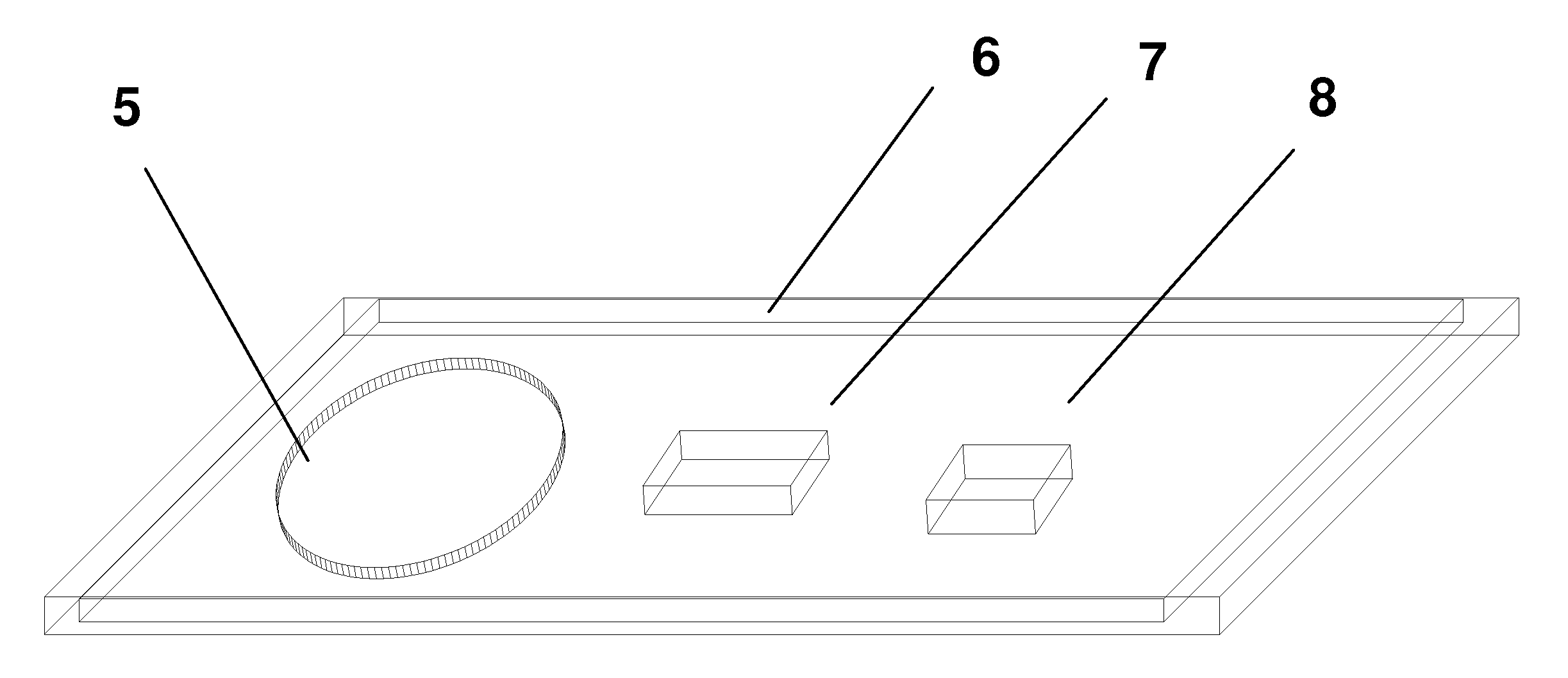
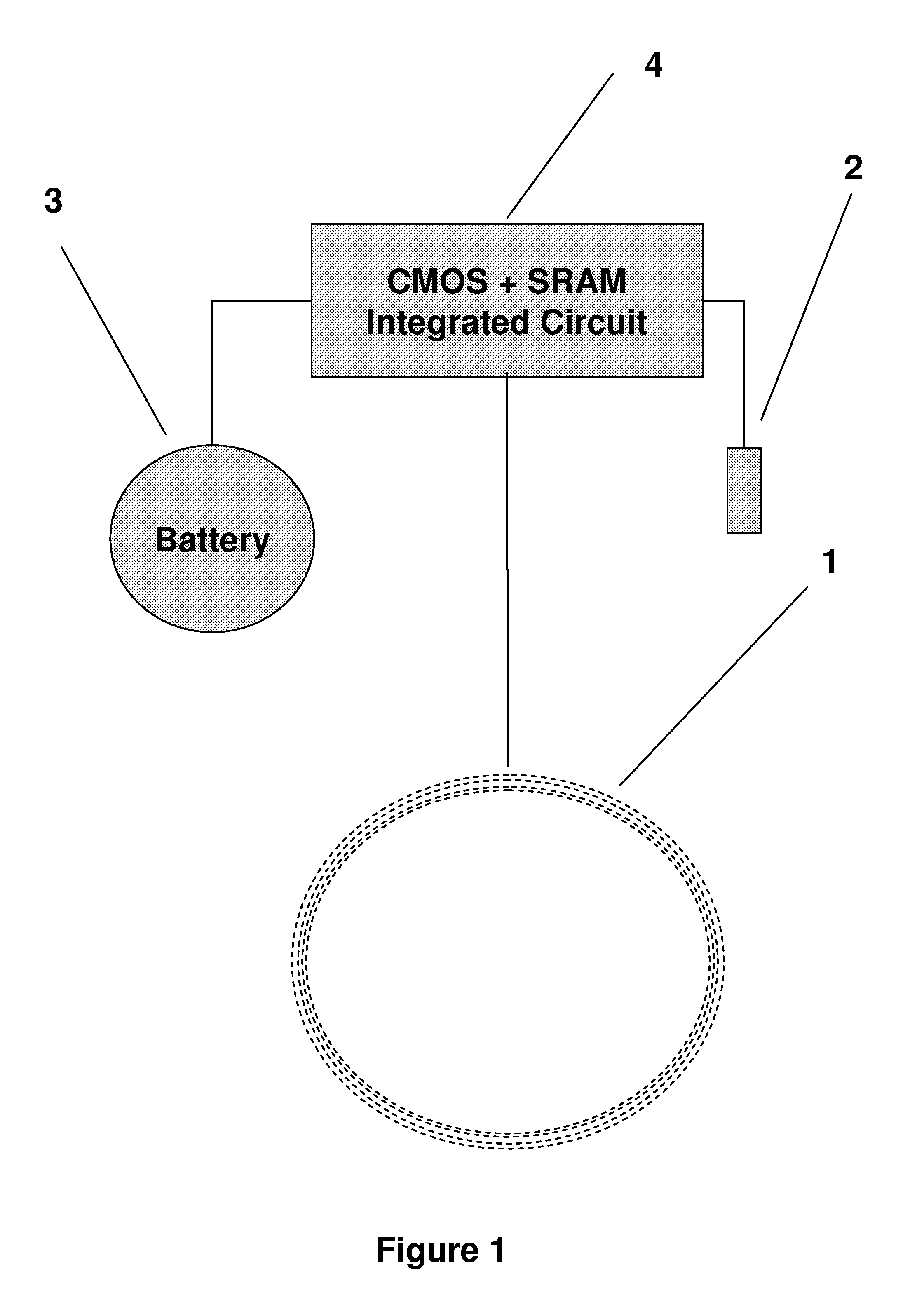
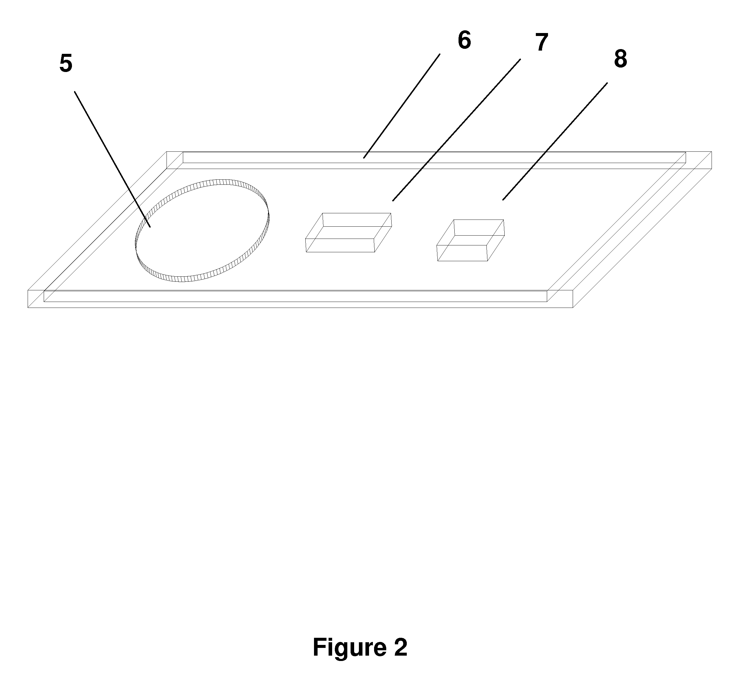
[0015] A sturdy radio tag has an antenna and semiconductor chip tuned to low frequency, encapsulated using a low-temperature and low-viscosity injection molding process.

Problems solved by technology

Active transceiver tags in the high-frequency range (433 Mhz) do exist (e.g. SaviTag ST-654), but are expensive (over $100.00 US) and large (videotape size, 6.25×2.125×1.125 inches) because of the power issues.
In previous disclosures we have shown that the prior art has assumed that low-frequency tags are slow, short-range, and too costly because of the antenna.
The art of encapsulating electronics is well known and was developed to produce packaged integrated circuits (U.S. Pat. No. 4,857,483) However, producing thin cards that meet the international thickness standard of 0.78 mm has created many special new problems.
Suspending the electronic devices within the thin card has been a challenge (US 5,955,021, US 6,025,054), and maintaining a commercial-grade card surface.
An additional serious problem has been that the lowest cost production method for these cards can only be achieved with high-pressure injection molding, similar to that used to encapsulate integrated circuits and other active components (US 4,043,027, US 3,367,025, US 4,857,483).
One major problem for many other electronic components such as batteries, capacitors, Liquid Crystal Displays (LCDs), and Light Emitting Diodes (LEDs) and crystals, is the fact that high-pressure injection molding may lead to elevated temperatures of over 200 C. for several minutes.
This can evaporate the electrolyte of a battery, and can either decrease the battery life or in some cases lead to a faulty battery.
It will destroy most LCDs, and many LEDs.
In some cases batteries and other components have been specifically designed to overcome these high-temperature effects (U.S. Pat. No. 5,089,877) but the cost of the high-temperature-resistant components may be several times greater than an equivalent low-temperature item.
This becomes more complex when a molded encapsulated product or device is created since the batteries cannot be replaced.
In some cases this problem has been solved by adding rechargeable batteries, however the elevated temperatures and complex chemistry make this an unattractive solution.

Method used


Image

  • Low-frequency radio tag encapsulating system
  • Low-frequency radio tag encapsulating system
  • Low-frequency radio tag encapsulating system

Examples


example # 1

EXAMPLE #1.

[0076]FIG. 15 shows a sturdy tag 36 according to the invention, placed on a two-inch granite slab 38, ready to be struck with a sledge hammer 37. The assignee was recently challenged by a well known RF-ID consultant regarding the tag packaging according to the invention. The consultant wondered whether the demonstration shown in FIG. 15 was contrived. The consultant wondered whether the assignee did not hit the tag very hard. Thus, the consultant bet the assignee that the assignee could not drive a nail into a piece of wood by hitting the tag 36 with a hammer. The terms of the bet were finalized—US $20.00 per nail, but limited to a total of three nails.

[0077]FIG. 16 shows a sturdy tag 36 according to the invention, nearby to a block of wood 40 with a small hole 41 in it, to be used for driving three nails42. The bet called for the use of the tag 36 and a hammer to pound three nails 42 into a wood block 39. A hard wood block 40 with a small hole 41 was placed over each na...

example # 2

EXAMPLE #2.

[0081]FIG. 22 shows a tongue 47 of a forklift (omitted for clarity in FIG. 22) positioned over a sturdy tag 36 according to the invention, in preparation for a test of the tag 36. The consultant proposed a new test, colloquially called the “Fork Lift Bash” or FLB. The tag 36 was placed under the tongue (fork) of a one-ton forklift. The end of the tongue is used to bash the tag 36 repeatedly. FIG. 23 shows the forklift 45 pushing down upon the tag 36 with enough force to lift both front wheels 46 of the forklift 45. This was repeated several times while the received signal from the tag 36 was monitored.

[0082]FIG. 24 plots tag reads with correct CRCs during the pressing or “bashing” activity of FIG. 23. The reads are plotted over time (horizontal axis) with the vertical axis showing received signal strength. The drops 48 in signal strength were due to detuning of the antenna because of the close contact to the steel in the tongue. Green dots in FIG. 24 represent reads that...


PUM


Abstract

A sturdy radio tag has an antenna and semiconductor chip tuned to low frequency, encapsulated using a low-temperature, low-pressure, low-viscosity injection molding process.

Description

[0001] This application claims priority from U.S. application No. 60 / 712,730 filed Aug. 29, 2006 and entitled “Low frequency radio tag and encapsulating system,” and from U.S. application No. 60 / 820,209 filed Jul. 24, 2006 and entitled “Tag challenge,” which applications are incorporated herein by reference for all purposes.FIELD OF THE INVENTION [0002] The present invention relates to a low-frequency radio transceiver tag encapsulated using a low-viscosity and low-temperature encapsulation method. This produces a sealed, low-cost long-range visibility system for use in a variety of different industries. BACKGROUND OF THE INVENTION [0003] Radio Frequency Identity tags or RFID tags have a long history and have been based largely upon the use of “transponders” tags that make use of a backscattered signal with a fixed pre-programmed ID. These tags are often designed to replace bar codes and are capable of low-power two-way communications. The first clear description of a transponder de...

Claims


Application Information

Patent Timeline
Patent Type & Authority Applications(United States)
IPC IPC(8): G08B13/14H01L23/02H01L23/28
CPCB29C45/14647B29L2031/3456G06K19/07749H01L23/49855H01L2924/0002H01L2924/00
Inventor STEVENS, JOHN K.WATERHOUSE, PAUL
Owner VISIBLE ASSET INC
Learn More