Lubricant applying unit, a process cartridge including the same, and an image forming apparatus provided with the process cartridge including the same

a technology of lubricant and application unit, which is applied in the direction of optics, instruments, electrographic processes, etc., can solve the problems of difficult to continuously apply a stable amount of lubricant for the entire surface and the life of the image bearing member may become longer. , to achieve the effect of reducing the frictional resistance produced and reducing the frictional resistan

Inactive Publication Date: 2007-07-26
RICOH KK
View PDF3 Cites 34 Cited by
  • Summary
  • Abstract
  • Description
  • Claims
  • Application Information

AI Technical Summary

Benefits of technology

[0028]In one exemplary embodiment, a novel lubricant applying unit includes a solid lubricant, a lubricant supporting unit configured to support the solid lubricant, a lubricant holder configured to accommodate the solid lubricant supported by the lubricant supporting unit, a pressing mechanism disposed between the lubricant...

Problems solved by technology

For example, the lubricant applying unit may solve problems when a cleaning brush or a cleaning blade remove residual toner remaining on the surface of the image bearing member after an image transferring operation has been performed.
When the surface of the image bearing member is coated with a lubricant, the life of the image bearing member may become longer.
On the contrary, it is difficult to remove the substantially spherical toner adhered or remaining on the surface of the image bearing member.
(1) A brush-type lubricant applying member rotates and scrapes a block-type solid lubricant so that the scraped lubricant in a powder form can be applied to the surface of the image bearing member.
(2) A lubricant is externally added to a toner particle. In this case, the amount of lubricant to be applied to the photoconductor may vary according to an image area to be output, and it is difficult to constantly apply a stable amount of lubricant for the entire surface of the image bearing member. Therefore, it is preferable to use a brush-type lubricant applying member to evenly apply a constant amount of lu...

Method used


Image

  • Lubricant applying unit, a process cartridge including the same, and an image forming apparatus provided with the process cartridge including the same
  • Lubricant applying unit, a process cartridge including the same, and an image forming apparatus provided with the process cartridge including the same
  • Lubricant applying unit, a process cartridge including the same, and an image forming apparatus provided with the process cartridge including the same

Examples


Embodiment Construction

[0070]In describing preferred embodiments illustrated in the drawings, specific terminology is employed for the sake of clarity. However, the disclosure of this patent specification is not intended to be limited to the specific terminology so selected and it is to be understood that each specific element includes all technical equivalents that operate in a similar manner.

[0071]Referring now to the drawings, wherein like reference numerals designate identical or corresponding parts throughout the several views, preferred embodiments of the present invention are described.

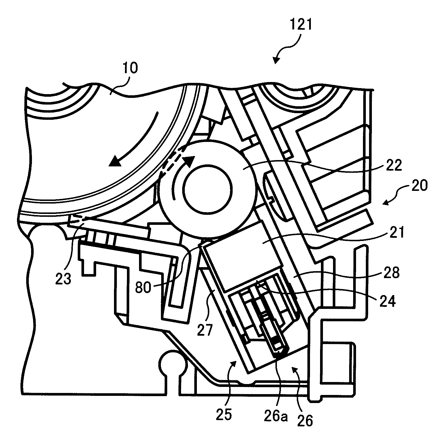
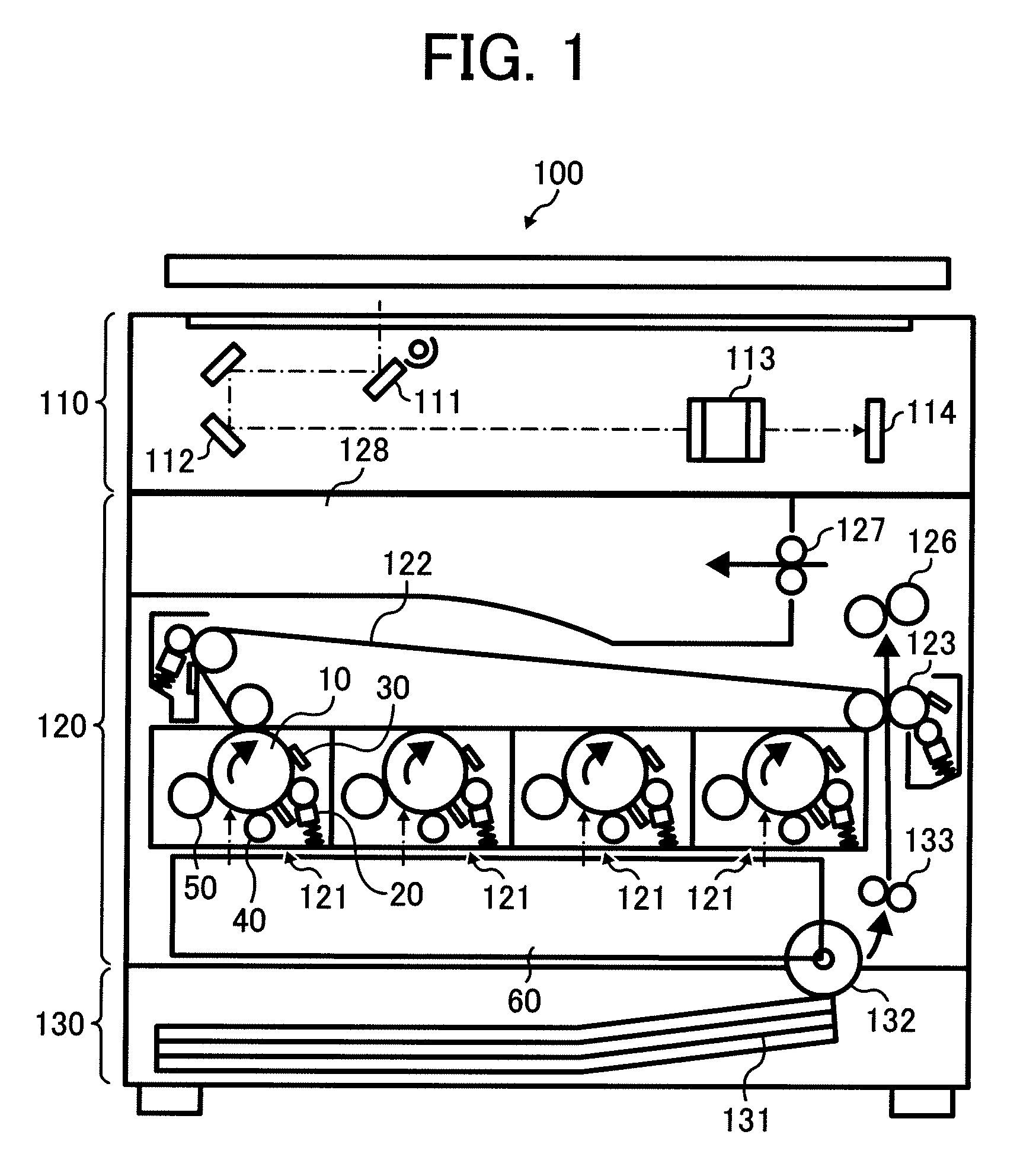
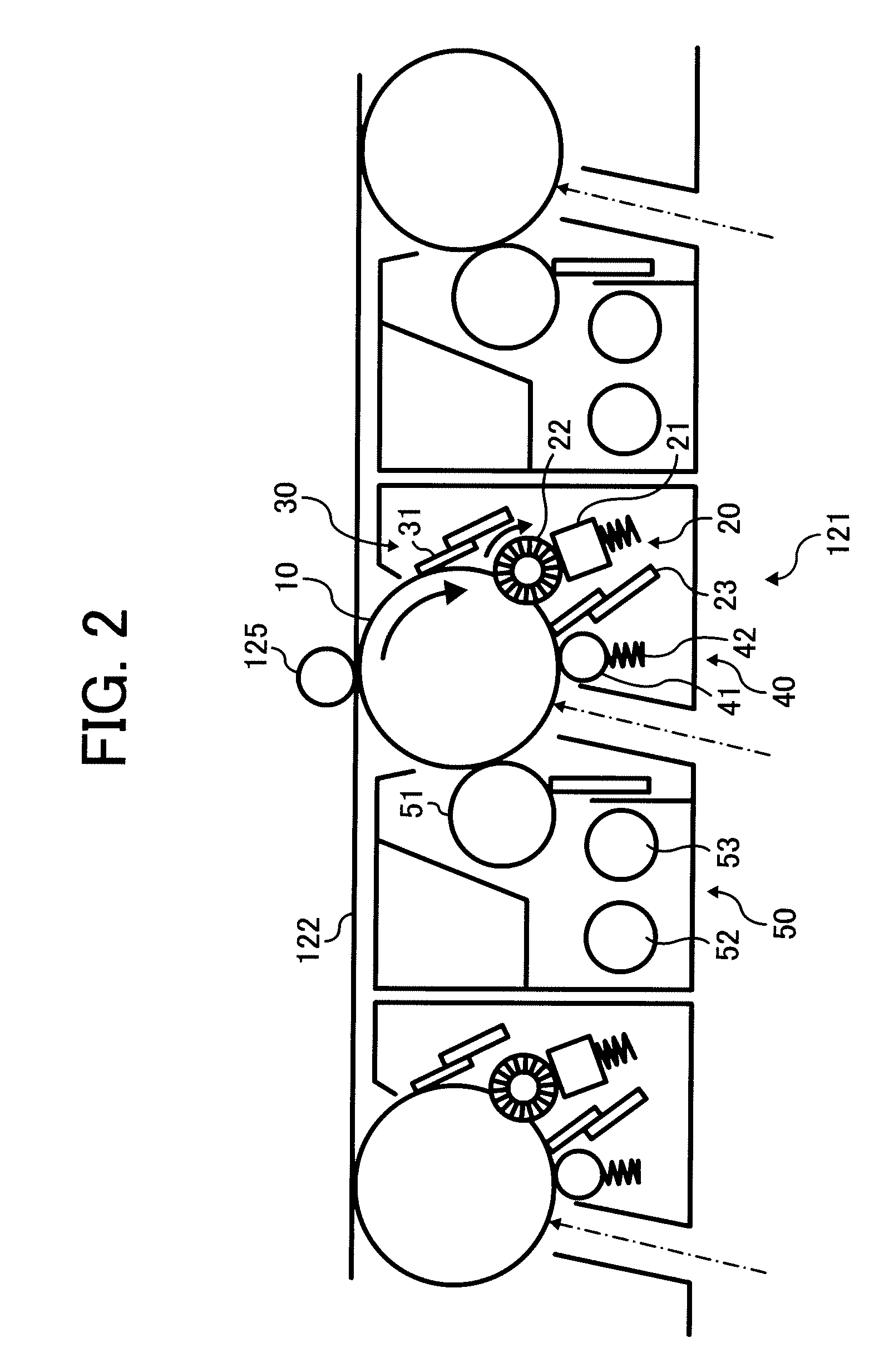
[0072]Referring to FIGS. 1, 2, and 3, a schematic entire structure and enlarged structures of an image forming apparatus 100 according to one exemplary embodiment of the present invention are described.

[0073]The image forming apparatus 100 of FIG. 1 may serve as a full-color image forming apparatus and include an image reading mechanism 110, an image forming mechanism 120, and a sheet feeding mechanism 130.

[0074]The ...


PUM


Abstract

A lubricant applying unit, included in a process cartridge provided in an image forming apparatus, includes a solid lubricant, a lubricant supporting unit to support the solid lubricant, a lubricant holder to accommodate the solid lubricant supported by the lubricant supporting unit, a pressing mechanism located between the lubricant supporting unit and the lubricant holder and designed to press the solid lubricant against a lubricant applying member, and a frictional resistance reducing member to reduce a frictional resistance produced at sliding contact portions between the lubricant supporting unit and internal surfaces of the lubricant holder.

Description

CROSS REFERENCE TO RELATED APPLICATIONS[0001]The present application claims priority to Japanese patent applications no. 2006-011881, filed in the Japan Patent Office on Jan. 20, 2006, no. 2006-013336, filed in the Japan Patent Office on Jan. 23, 2006, and no. 2006-101787, filed in the Japan Patent Office on Apr. 3, 2006, the disclosures of each of which are incorporated by reference herein in their entirety.BACKGROUND OF THE INVENTION[0002]1. Field of the Invention[0003]The present invention relates to a lubricant applying unit, a process cartridge including the lubricant applying unit, and an image forming apparatus provided with the process cartridge including the lubricant applying unit. More particularly, the present invention relates to a lubricant applying unit that applies a lubricant on a surface of an image bearing member and forms a thin layer of the lubricant, a process cartridge that includes the above-described lubricant applying unit, and an image forming apparatus th...

Claims


Application Information

Patent Timeline
IPC IPC(8): G03G21/00
CPCG03G2221/1609G03G21/0094G03G2221/1627
Inventor HARADA, HIROOMITANAKA, SHUJIKUMAGAI, NAOHIRO
Owner RICOH KK
Why Eureka
Try Eureka