Fan and impeller thereof

a technology of a fan and an impeller, which is applied in the direction of liquid fuel engines, vessel construction, marine propulsion, etc., can solve the problems of reducing the performance of the fan b>1/b, generating noise, and affecting the performance of the fan b>, so as to reduce noise, reduce air resistance, and increase air-intake efficiency

Active Publication Date: 2007-07-26
DELTA ELECTRONICS INC
View PDF5 Cites 6 Cited by
  • Summary
  • Abstract
  • Description
  • Claims
  • Application Information

AI Technical Summary

Benefits of technology

[0016]As mentioned above, the fan and impeller of the invention have at least one airflow-guiding portion for increasing the air-inlet area or changing the airflow field of the air entering the blades. Thus, the air resistance can be reduced and the air-intake efficiency can be increased. Accordingly, the vortexes and airflow separation phenomenon may be avoided, the noise is decreased, and the performance of the fan can be enhanced.

Problems solved by technology

However, when the curvature of the guiding angle 1111 is increased, the air-inlet end of the blades 112 may form an air resistant area with a large turn, which decreases the performance of the fan 1.
This will affect the performance of the fan 1 and generate the noise.

Method used


Image

  • Fan and impeller thereof
  • Fan and impeller thereof
  • Fan and impeller thereof

Examples


Embodiment Construction

[0023]The present invention will be apparent from the following detailed description, which proceeds with reference to the accompanying drawings, wherein the same references relate to the same elements.

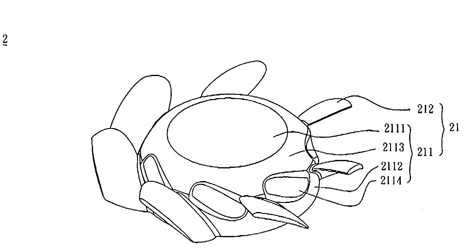
[0024]With reference to FIG. 3, a fan 2 according to a preferred embodiment of the invention includes an impeller 21 and a motor (not shown). The fan 2 may be an exterior-rotor axial-flow fan or an interior-rotor axial-flow fan. The motor connects to the impeller for driving the impeller to rotate. The motor may be set in the impeller 21 or out of the impeller 21.

[0025]The impeller 21 includes a hub 211 and a plurality of blades 212. The hub 211 has a top portion 2111, a connection portion 2112, and at least one airflow-guiding portion 2114. In this embodiment, the airflow-guiding portion 2114 is disposed between two adjacent blades 212 and is extended to the top portion 2111. In addition, the first airflow-guiding portion 2114 can be contacted with adjacent two of the blades 212. The...


PUM


Abstract

A fan includes an impeller and a motor. The impeller includes a hub and a plurality of blades. The hub has a top portion, a connection portion, and at least one airflow-guiding portion. The top portion is connected to the connection portion. The blades are disposed around the connection portion. The motor is disposed corresponding to the impeller and used to drive the impeller to rotate. The airflow-guiding portion is disposed between two adjacent blades.

Description

BACKGROUND OF THE INVENTION[0001]1. Field of Invention[0002]The invention relates to a fan and an impeller thereof, and, in particular, to a fan and an impeller thereof that can reduce noise and increase airflow quantity.[0003]2. Related Art[0004]Since the present electronic products are rapidly developed towards high performance, high frequency, high speed and more compact, the generated heat of the electronic products becomes greater. Utilizing a fan to dissipate the heat generated by the electronic products is a common solution. In this case, the airflow pressure and the airflow quantity of the fan are important reference factors for determining the performance of the fan. Besides, the noise of the fan is also an important reference factor for the fan.[0005]As shown in FIG. 1, a conventional fan 1 includes an impeller 11 and a motor (not shown). The impeller 11 includes a hub 111 and a plurality of blades 112, which are connected to and disposed around the periphery of the hub 11...

Claims


Application Information

Patent Timeline
Patent Type & Authority Applications(United States)
IPC IPC(8): F01D1/02
CPCF04D29/329
Inventor HO, SHIHHUAHUANG, SHIHYINGLEI, TSUNG-YULAN, CHUNG-KAICHEN, HUAN-CHIHUANG, WEN-SHI
Owner DELTA ELECTRONICS INC
Why Eureka
Try Eureka