System and Method to Control Energy Input to a Material

Inactive Publication Date: 2007-08-02
THE SHERWIN-WILLIAMS CO
View PDF44 Cites 7 Cited by
  • Summary
  • Abstract
  • Description
  • Claims
  • Application Information

AI Technical Summary

Benefits of technology

[0008] A further embodiment of the present invention comprises a system for controlling energy that is input to a material substance for the controlled removal of moisture from the material substance. The system comprises a cooling/de-humidification subsystem for accepting ambient air and for decreasing a temperature level and/or a humidity level of the ambient air to produce a relatively dry and cool pre-conditioned air. The system further comprises a heating/humidification subsystem operationally connected to the cooling/de-humidification subsystem to accept the pre-conditioned air and to add thermal energy and moisture to the preconditioned air to produce a controlled air having a specified humidity level at a specified temperature level. The system also comprises an energy transfer chamber operationally connected to the heating/humidification subsystem to accept the controlled air such that the controlled air passes across a material substance within the energy transfer chamber and transfers thermal energy from the controlled air to the material substance, thereby causing at least one outer surface of the material substance to lose moisture in a controlled manner. The system further comprises a variable power microwave source operationally connected to the energy transfer chamber to provide microwave energy into the energy transfer chamber such that the material substance may absorb at least a part of the microwave energy and convert the absorbed microwave energy to thermal energy within the material substance, thereby causing at least an internal volume of the material substance to lose moisture in a controlled manner.
[0009] Another embodiment of the present invention comprises a method of controlling energy that is input to a material substance for the controlled removal of moisture from the material substance. The method includes providing an in-bound ambient air volume flowing at a specified flow rate. The method furt

Problems solved by technology

That is, wet paint does not reflect the

Method used


Image

  • System and Method to Control Energy Input to a Material
  • System and Method to Control Energy Input to a Material
  • System and Method to Control Energy Input to a Material

Examples


Example

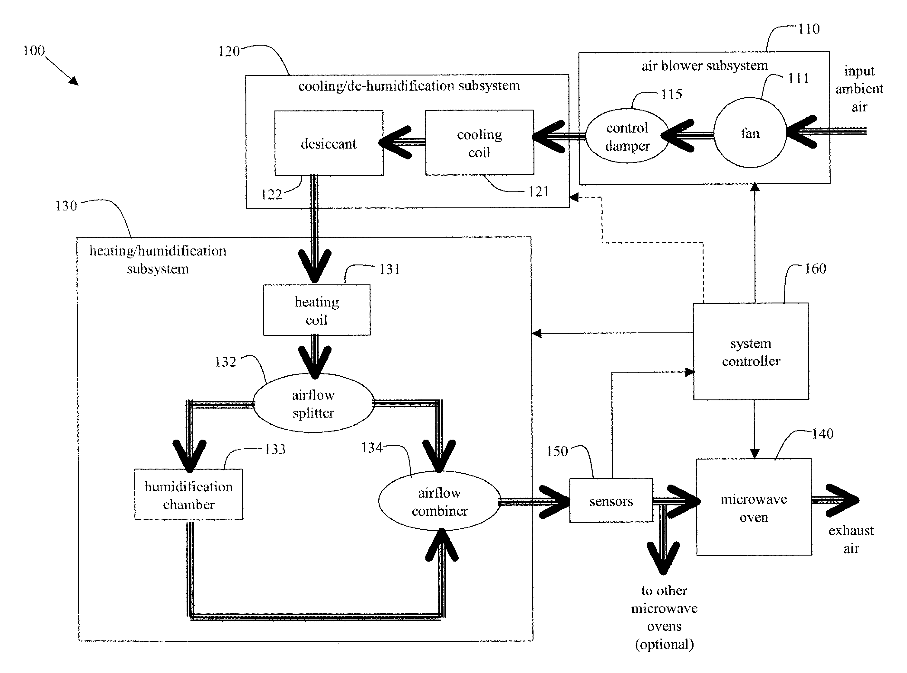
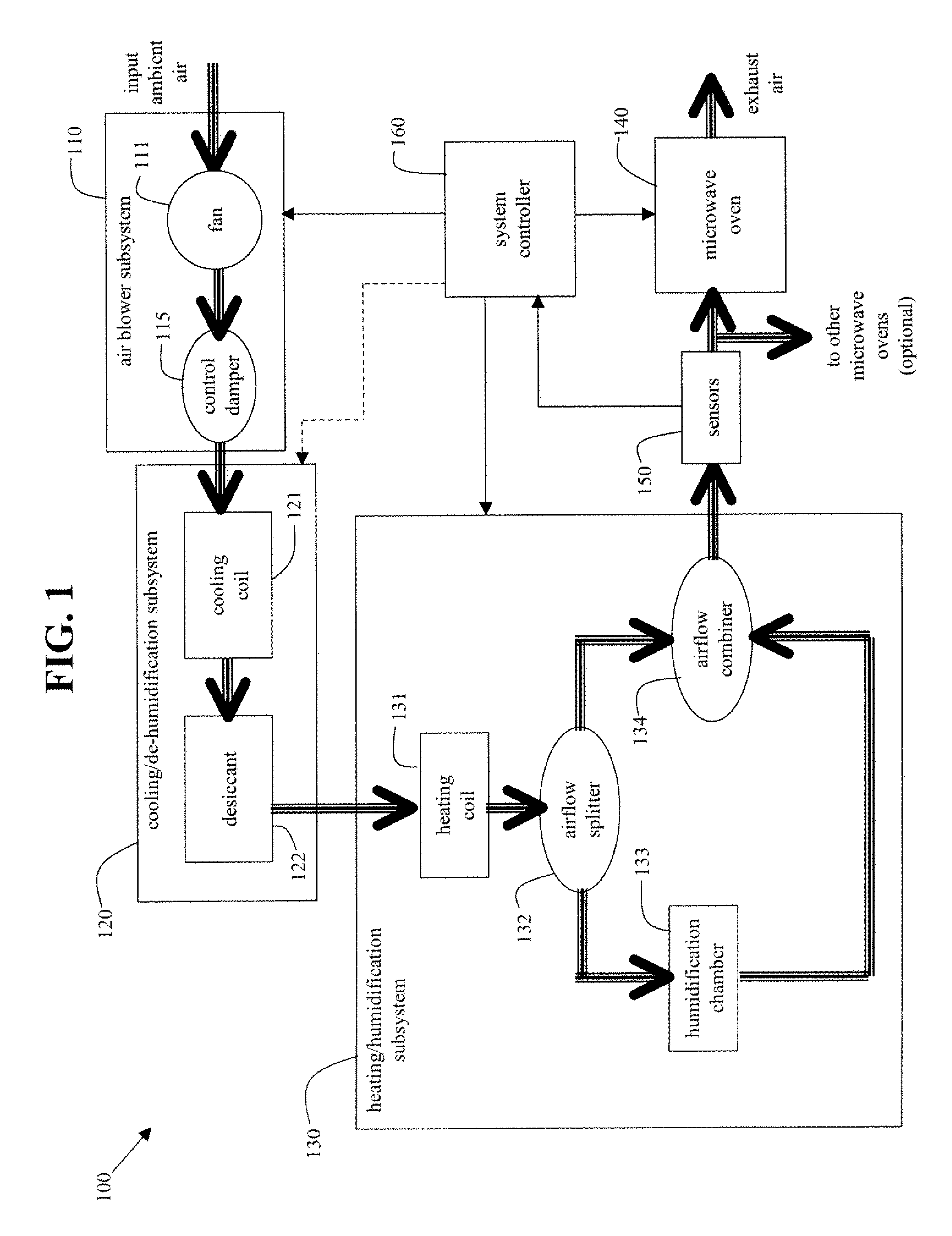
[0016]FIG. 1 illustrates a schematic block diagram of an exemplary embodiment of a system 100 for controlling energy that is input to a material substance, in accordance with various aspects of the present invention. The system 100 includes an air blower subsystem 110 to blow ambient air into the system 100 and to control the flow rate of air within the system 100. In accordance with an embodiment of the present invention, the air blower subsystem 110 includes a fan ill and a control damper 115. The system 100 further includes a cooling / de-humidification subsystem 120 operationally connected to the air blower subsystem 110 for accepting ambient air and decreasing a temperature level and / or a humidity level of the ambient air to produce a pre-conditioned air which is relatively dry and cool. In accordance with an embodiment of the present invention, the cooling / de-humidification subsystem 120 includes a cooling coil 121 and a desiccant 122.

[0017] The system 100 also includes a heati...


PUM

PropertyMeasurementUnit
Fractionaaaaaaaaaa
Temperatureaaaaaaaaaa
Timeaaaaaaaaaa

Abstract

A system and method of controlling energy that is input to a material substance, for the controlled removal of moisture from the material substance, is disclosed. A controlled air flow is blown onto the material substance at a specified air flow rate over at least one specified time period such that the material substance absorbs thermal energy from the controlled air flow via at least one outer surface of the material substance. The controlled air flow is of a specified humidity level at a specified temperature level. The material substance is also irradiated with microwave energy at a first specified power level for at least a first specified time duration such that the material substance absorbs at least a part of the microwave energy and converts the absorbed microwave energy to thermal energy within the material substance. As a result, moisture is removed from the material substance in a controlled manner.

Description

CROSS-REFERENCE TO RELATED APPLICATION [0001] This application claims the benefit of U.S. provisional patent application No. 60 / 739,693 filed on Nov. 23, 2005, the entirety of which is hereby incorporated by reference.TECHNICAL FIELD [0002] Certain embodiments of the present invention relate to transferring energy to a material substance. More particularly, certain embodiments of the present invention relate to a system and method to transfer thermal energy and microwave energy to a material substance for the purpose of removing moisture from the material substance in a controlled manner to affect, for example, a desirable characteristic of the material substance, such as color appearance of the material substance. BACKGROUND OF THE INVENTION [0003] Many times in industry, processes are needed for removing moisture from material substances. For example, in the paint industry during the manufacturing of paint, quality control procedures are implemented to check the true colors of pai...

Claims


Application Information

Patent Timeline
IPC IPC(8): F26B3/347
CPCF26B21/06F26B3/343
Inventor PATKA, JOHN J. SR.JUDGE, SHARON L.
Owner THE SHERWIN-WILLIAMS CO
Why Eureka
Try Eureka